Hi all,
I have an faulty Oberheim Xpander japanese version. The problem comes from SMPS PSU. I already replaced the switcher transistor T1 2SC3262, bridge D1 and the resistor R1 on the below schematic because these parts where dead. I did replace R1 with a 10ohm 5W as I couldnt read the original value as it has burned. If someone nows a good value for R1?
Now the PSU works with no load, I have the right voltage. When I connect it to the synth boards all the voltage fall down and the Xformer L1 start to buzz a little.
I have removed the PSU from the synth and bench test it.
As soon I try to load the output of the PSU the voltage collapse.
I load a 240ohms on the +12V (or -12,+55) the voltage collapse to 6V.
And 240ohm is not a big load considering all the electronic that is inside this synth.
Can it be L1 that has burned is some way? Or what looks strange to me is the rectified 220VAC (first scope pict)
I took some scope pics from various parts.
Schematic
Bridge D1 A-B 100V/div 5ms/div
Across L1 100V/div 5ms/div
T1 base 1V/div 10us/div
T1 collector to emitter 100V/div 5us/div
Pin 11 from U1 MB3759 10V/div 10us/div
I have an faulty Oberheim Xpander japanese version. The problem comes from SMPS PSU. I already replaced the switcher transistor T1 2SC3262, bridge D1 and the resistor R1 on the below schematic because these parts where dead. I did replace R1 with a 10ohm 5W as I couldnt read the original value as it has burned. If someone nows a good value for R1?
Now the PSU works with no load, I have the right voltage. When I connect it to the synth boards all the voltage fall down and the Xformer L1 start to buzz a little.
I have removed the PSU from the synth and bench test it.
As soon I try to load the output of the PSU the voltage collapse.
I load a 240ohms on the +12V (or -12,+55) the voltage collapse to 6V.
And 240ohm is not a big load considering all the electronic that is inside this synth.
Can it be L1 that has burned is some way? Or what looks strange to me is the rectified 220VAC (first scope pict)
I took some scope pics from various parts.
Schematic
An externally hosted image should be here but it was not working when we last tested it.
Bridge D1 A-B 100V/div 5ms/div
An externally hosted image should be here but it was not working when we last tested it.
Across L1 100V/div 5ms/div
An externally hosted image should be here but it was not working when we last tested it.
T1 base 1V/div 10us/div
An externally hosted image should be here but it was not working when we last tested it.
T1 collector to emitter 100V/div 5us/div
An externally hosted image should be here but it was not working when we last tested it.
Pin 11 from U1 MB3759 10V/div 10us/div
An externally hosted image should be here but it was not working when we last tested it.
1) the 10R is only to limit inrush, so the value is not critical.
2) Try to load only the voltage sensed output, in fact the winding that appears to have 45V. In such case, the voltage must be stable. If this is the case, the SMPS needs load proportional in all outputs.
Check base resistors and the IC, appears that it has the driver build in and may be fake. Also, recap all the supply, and use 105deg and low ESR caps.
Keep us posted.
Good luck.
Thanks Osvaldo, I did load the sensed output (+5V not 45) with 10ohm and the + and - 12v with 100ohm each and the the voltage is stable. So I think now smps works.
When I connect it to the boards then the -12 drops to -10.5, +12 to 11.5 and the +5v to 4.7V. The +55v is stable and the 9VAC too.
Unfortunately the synth is not working. The three Vacuum Fluorescent Display
are black and no reaction when pressing any knob.
As I dont have the corect schematic (the synth is the japanese version), only for american version avaible, and the service manual does not match to the boards.
Im stuck now until I find a japanese service manual. If someone now where to find it...🙁
> Bridge D1 A-B 100V/div 5ms/div
You should have ~300V DC there, not pulsating. Looks like your primary-side smoothing caps are bad or have a bad connection.
You should have ~300V DC there, not pulsating. Looks like your primary-side smoothing caps are bad or have a bad connection.
hello, i'm happy owner of a xpander
i have problem with power supply board since two days ..
xpander shout out in middle of project..
resistor R4, R17 had burn out
we replace R4, R17, so the x pander start again, good
but after 2 min, resistor R17 goes too hot again and smoky ..
so we replace also transistor Q2, Q3, and capacitor C15 ..
big signal transformer (fixed on metal case) delivery 13v
and his extension look ok as the guy say .. i don't know ..
What can make resistor R17 overheating ?
i have photos, good shematic here : http://www.synfo.nl/servicemanuals/Oberheim/XPANDER_SERVICE_MANUAL.pdf
cheers from paris
hello gmphadte,
D9 , capacitor Q2, Q3, circuit U4, circuit in center of Q1 have been change by new..
the pro technician tell me today,
transfo driver 8103-TI 8430W T1 is not working.
they are no equivalent, we need the original he tell me..
How to find this ?
last chance is to build external power supply for the 4 voltage circuit..
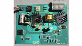
photo are before the work.
D9 , capacitor Q2, Q3, circuit U4, circuit in center of Q1 have been change by new..
the pro technician tell me today,
transfo driver 8103-TI 8430W T1 is not working.
they are no equivalent, we need the original he tell me..
How to find this ?
last chance is to build external power supply for the 4 voltage circuit..
photo are before the work.
Attachments
i still looking for this flyback transfo . XFMR 3Okhz from old oberheim period.
Any info welcome ( old stock store ) ..
photos:
14/26/beem.jpg - Visionneuse Zupimages
14/26/j3df.jpg - Visionneuse Zupimages
14/26/k5pz.jpg - Visionneuse Zupimages
somebody know his caracteristic in / out voltage, watt, ampere ?
or what's the caracteristic (watt, ampere) of the four circuits to power the xpander ,
+ 55v. -12v +12v. -5 +5v. 9 vac in case of building new external power supply ..
best vibes
- Status
- Not open for further replies.
- Home
- Amplifiers
- Power Supplies
- SMPS PSU from Oberheim Xpander not working need help