Hi to all. I made SMPS by Azmi but with little modification because I cant find all components in my country.
- For mosfets i use cheap IRF740 with 10R gate resisotor (final circuit will be with IRFP460)
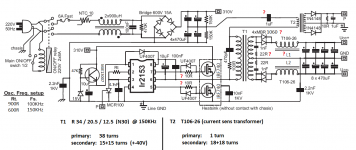
- Main transformer is toroid R34/20.5/12.5 (N30 - only that I can find) pri: 38turns sec:15+15 turns for +-40V
- Osc.freq is 150Khz because I need max power from transformer (aprox. 500W max)
- I have 2 x 3.2K on output between main rails and GND (dont have on schematics)
-Part with MJE13007 is for IR2153 aux supplay and that transistor is on heatsink and its HOT (its normal I think)
-Heatsink with main mosfets are cold but other heatsink with MBR1060 diodes are very hot after few seconds from turning on and caps and inductors are hot too.
This SMPS is working but I have few questions.. (Red question marks on schematics)
1) First time AUX supplay for IR2110 was 11.4V and after 10 minutes only IC was died, I replace IC and its working again. Can low voltage be a reason for that crush?
2) For that freq. (150KHz) do I need different value for gate resistor for IRF740 and IRFP460?
3) Are snubber values for primary and secondary good? Do I need to change something in snubbers network? (pri: 100R + 470pF sec: 2 x 22R + 1nF)
4) Can I use T106-26 for output inductor and which value I need? First I use 40uH but diodes, caps and that two inductors were very hot. With 20uH, temperature is decrise but both diodes (MBR1060) are died after few seconds without load, do i need to change diodes on example BYW29???
5) Why output diodes (MBR1060) are to hot after few seconds without load??? (Only load is 2 x 3.2K on output between main rails and GND?
6) Capacitor 1uF in series with primary, is it have good value or I need to increase it to 2.2uF?
7) For more power, can I use two of this toroids? (I think in this case I will need only half of number of turns for primary and half for secondary for same voltage but bigger power)?
8) Is everything else allright?
Thanks and regards, Nikola
- For mosfets i use cheap IRF740 with 10R gate resisotor (final circuit will be with IRFP460)
- Main transformer is toroid R34/20.5/12.5 (N30 - only that I can find) pri: 38turns sec:15+15 turns for +-40V
- Osc.freq is 150Khz because I need max power from transformer (aprox. 500W max)
- I have 2 x 3.2K on output between main rails and GND (dont have on schematics)
-Part with MJE13007 is for IR2153 aux supplay and that transistor is on heatsink and its HOT (its normal I think)
-Heatsink with main mosfets are cold but other heatsink with MBR1060 diodes are very hot after few seconds from turning on and caps and inductors are hot too.
This SMPS is working but I have few questions.. (Red question marks on schematics)
1) First time AUX supplay for IR2110 was 11.4V and after 10 minutes only IC was died, I replace IC and its working again. Can low voltage be a reason for that crush?
2) For that freq. (150KHz) do I need different value for gate resistor for IRF740 and IRFP460?
3) Are snubber values for primary and secondary good? Do I need to change something in snubbers network? (pri: 100R + 470pF sec: 2 x 22R + 1nF)
4) Can I use T106-26 for output inductor and which value I need? First I use 40uH but diodes, caps and that two inductors were very hot. With 20uH, temperature is decrise but both diodes (MBR1060) are died after few seconds without load, do i need to change diodes on example BYW29???
5) Why output diodes (MBR1060) are to hot after few seconds without load??? (Only load is 2 x 3.2K on output between main rails and GND?
6) Capacitor 1uF in series with primary, is it have good value or I need to increase it to 2.2uF?
7) For more power, can I use two of this toroids? (I think in this case I will need only half of number of turns for primary and half for secondary for same voltage but bigger power)?
8) Is everything else allright?
Thanks and regards, Nikola
Attachments
The IR2153 has a under voltage shutdown it only will send signals to the output transistors until it reaches a constant supply voltage, also you will need to be sure your mosfets have a low Cg to ensure those turn off and on properly the IR2153 only can switch like 5mA per output or so, you should change those diodes to some 200 volts or so per diode, also you can have lots of harmonics at the ouput diodes or higher voltage peaks when no loads, remember its a self-oscilating and its free of regulation.
That capacitor seems to fine you could try a 1.5uF of at least 450V
That capacitor seems to fine you could try a 1.5uF of at least 450V
Last edited:
Thank for answer.. What about other parts on schematic, is everything is good?
What about gate resisotor, output inductor value and double core with half of turns?
Is it true that SMPS without feedback dont need output inductor, because of duty cycle of continius 50%
What about gate resisotor, output inductor value and double core with half of turns?
Is it true that SMPS without feedback dont need output inductor, because of duty cycle of continius 50%
All seems correct, those mosfets seem fine for some 250-300 watts but for no more, also those have a low Cg so it wouldn´t cause so much trouble driving them, you may want to have a good layout, since this ICs are too much sensitive to stray currents or to electrostatic.
A good place to search info of the transformer construction is this:
Power Transformer & Inductor Design
In summary:

A good place to search info of the transformer construction is this:
Power Transformer & Inductor Design
In summary:
- Vin Nominal Input Voltage. (Voltage of the rectified line)
- F Operating switching frequency in Htz.
- Bmax Maximum flux density in Gauss. (1 T = 10 000 G)
- Ac Effective Cross-Sectional Area in cm2
- Npri Primary calculated Turns
Last edited:
Pd: In your case you will need to divide by two Vin because you have a voltage divider in the supplyAll seems correct, those mosfets seem fine for some 250-300 watts but for no more, also those have a low Cg so it wouldn´t cause so much trouble driving them, you may want to have a good layout, since this ICs are too much sensitive to stray currents or to electrostatic.
A good place to search info of the transformer construction is this:
Power Transformer & Inductor Design
In summary:
First you need to know the maximum operating flux density of your toroid or ferrite core, and choose a good compromise between power and regulation, if you choose a high value you could saturate the core leading to overheating and thermal problems, if you choose a lowish value, then you are missusing the core, and you will getting lower output power, you can choose something in between 70 - 90% of the B max without too much trouble, also you need to take in count the voltage in the primary when loaded since the current would decrease the available voltage for the primary, for the secondary you take the final Npri turns and divide it by the primary available voltage leading to a turns per volt and finally appling the same turns per volt for the output and then you have the secondary turns, be sure to leaving a margin for the secondary load beacause this does not have a feedback sensing so it wont regulate when loaded.
- Vin Nominal Input Voltage. (Voltage of the rectified line)
- F Operating switching frequency in Htz.
- Bmax Maximum flux density in Gauss. (1 T = 10 000 G)
- Ac Effective Cross-Sectional Area in cm2
- Npri Primary calculated Turns
View attachment 427931

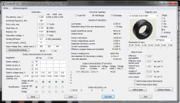
For transformer calculation I use ExcellentIT softwere. My transformer:
- Effective preambility 4300 (N30 material), because of that I have to push it on high freq (150KHz) because N30 on high freq is more like N27 material (Lower flux denisty), higher output power and lower number of turns
- Ae 82.6 mm2
- An 202 mm2
- Le 82.6 mm
- Ve 6.778 mm3
- Flux denisty (on 150KHz) will be 0.090T or 900G
- Input voltage 320VDC / 2 = 160VDC but lowest expect 125VDC (duty cycle 50%)
With all of that I calculated number of turns for transformer and everything is allright..
I plan to use 2 of this transforemer cores for 1KW of power.
When I calculate two of this cores like they are one, only double Ae value and Ve value.
Area of core window (An) and Langht of magnetic path (Le) stay the same, and claculation says that whole number of turns are decrise for half, all condition is the same.. Is it corect?
- When I use MBR1060 diodes, thay are very hot after few seconds with or without load, output inductor is very hot too and first value was 40uH, fileter cap are hot too. Than I place dumy load 2 x 3.2K between gnd and main ouptut rails, decrise output inductor to 20uH. Temperature were decrise for half but both diodes were died when I only start up the SMPS. Output voltage were +-43V and didodes were for 60V, maybe I have to use some 200V diodes like BYW29? What do you think about that?
- Tell me more about output inductor value (can I use T106-26 core)?
- Tell me about gate resistor for on example IRFP460, because IRF740 is only for testing and low power.
- Tell me about snubbers for primary and secondary? Do I need snubbers on secondary side?
* I uploaded print screen of my calculation for transformer (one core)
Attachments
output rectifier should be arranged in bridge configuration mode, selection of rectifier is also wrong, should be at least 200v
Last edited:
For the IRFP460 you will need a output transistor totem pole, because this mosfets have a high Cg so it would have problems to correctly switch on and off the mosfets (cross-conduction issues), also for that you need a beefier steady 12- 14 volts for supply (at least for some 50mA), that core seems fine for the output you can also use a iron powder (like the green ones in a PC power supply), and yes you will also need snubbers in the secondary.
Those BYW29 have a good ttr (reverse recovery time) for your purposes
Those BYW29 have a good ttr (reverse recovery time) for your purposes
Last edited:
- Status
- Not open for further replies.
- Home
- Amplifiers
- Power Supplies
- SMPS IR2153 problem and review