Hello
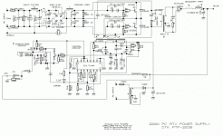
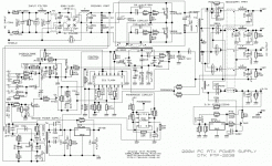
Today I converted 400W ATX power supply to one output with 35V and 10A. I would be very happy if you check my shematic if there is anything wrong, as I am going to draw PCB, because I need to build several units.
Output inductor with yellow ring core has 25 turns. Other inductor is taken from 12V line and has approximately 20 turns around ferite core. I am not sure if inductance of those inductors is suitable, but it somehow works. If you know what inductances should be, please tell me. Is there any way to use only one inductor (only yellow ring core)?
Transformer has only 15 + 15 turns at secondary. Is this enough for 35V? Originaly transformer had 7 turns for 12V, but I dont have enough space for 20+20 turns.
Please check also overvoltage/overcurrent circuit if everything looks OK and tell me what shuld be values for output snubber resistor and capacitor. Currently PSU works without them.
ON-OFF switch will be placed on primary side of 230V-9V transformer. Will this work or should I chose a different way?
(I edited original shematic of ATX power supply in MS Paint
😀)
Thanx
Attachments
Im
Hello Primoz
These days im also design 15V/20A power supply.I think ur transformer calculations are ok.
Im also going to do same method u using here.But for control circuit im using LM339 comparator.and for secndry power supply im using TNY256P as your transformer supply.so will post my circuit diagram.ur circit diagram has short circuit protection?
Regards
Dhanuka
Yes, it has short circuit protection, but I didnt test if it works. If voltage at base of Q7 gets too high, PSU turns off.
You gave me nice idea about using LM339, as i have a lot of this comparators at home.
You gave me nice idea about using LM339, as i have a lot of this comparators at home.
Today I was testing my prototype or if I'm more specific I was blowing up transistors 😀
I've learned this:
I will make new protection circuit using comparators to measure current, voltage and temperature. What do you think about measuring current at secondary side?
I've learned this:
This was VERY bad idea. When i turned off this transformer, power supply started to oscilate by itself and at output I measured 52V under 5A load 😱ON-OFF switch will be placed on primary side of 230V-9V transformer. Will this work or should I chose a different way?
I think inductance of output inductor is far from being right, because transformer starts to make strange noises when current is over 4A. This never hapens with my 13.8V 25A power supply which I made several years ago out of old AT PSU. I will try 22uH.Output inductor with yellow ring core has 25 turns. Other inductor is taken from 12V line and has approximately 20 turns around ferite core. I am not sure if inductance of those inductors is suitable, but it somehow works. If you know what inductances should be, please tell me. Is there any way to use only one inductor (only yellow ring core)?
I can tell you now that it doesn't work. Reason is that R44 is too big, but after replacing it with lower value it still doesn't work as it should. I don't know why, but after it's activated, tl494 doesn't turn off, but just lowers output voltage a bit. If I make short circuit at output, transistors just blow. Probably there is something wrong in my circuit, as overvoltage protection somehow works.Yes, it has short circuit protection, but I didnt test if it works. If voltage at base of Q7 gets too high, PSU turns off.
I will make new protection circuit using comparators to measure current, voltage and temperature. What do you think about measuring current at secondary side?
- Status
- Not open for further replies.

