 Thread closed. This project was an example of unsafe practice in that all the primary side electronics are unisolated from the mains and consequently LIVE at all times. Without specialist knowledge and the correct equipment this type of supply can be lethal to work on and lethal to others. Also see section 2 in the notes here,
http://www.diyaudio.com/forums/site-announcements/167561-diyaudio-rules.html
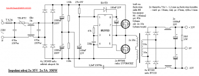
To drive my ClassD Amp, i have just started building an SMPS from the following schematic (see attachments)
The layout is also provided in the attachments - sorry for bad part naming! - what's your opinion about this one?
For Copyright Claimers: the schematic is not my creation, but the layout is.
thanks in advance 🙂
PS: The yellow tracks show wire bridges, as i didnt want to make it double-sided.
Attachments
Last edited by a moderator:
Hi Nigel
greetings any tips how to implement voltage feedback for line regulation please see SCHEMATIC on thread by me smps schematic attached
warm regards
andrew
greetings any tips how to implement voltage feedback for line regulation please see SCHEMATIC on thread by me smps schematic attached
warm regards
andrew
On your PCB does not seem to be much room for creepage and clearance - is it OK?
Does your core actually handle 350W?
Does your core actually handle 350W?
As it is a EE42 Core, the power handling will be a trial and error determination 😀
That is okay, i reduced the tracks manually where they were too close.
But i've got some part placement problems 🙁 it's gonna be a thight fit in that enclosure ...
That is okay, i reduced the tracks manually where they were too close.
But i've got some part placement problems 🙁 it's gonna be a thight fit in that enclosure ...
The irs27951 looks a bit better as it has a feedback loop to keep the output voltage the same.
I don't think you need the half dc voltage splitter circuit as the circuit is AC coupled anyway.
I don't think you need the half dc voltage splitter circuit as the circuit is AC coupled anyway.
Kinda scary with offline SMPS...Hope you know what your doing🙂
Is that a simplified circuit? No gate resistors? Kinda huge boost-cap? That halfbridge driver with built in oscillator has no feedback input. I guess you can free-run it, but you'll need to regulate the secondary. You can probably use the C input to control the duty cycle. A proper SMPS will regulate the output and give you short circuit protection.
I seriously doubt that transformer will handle that much power at that frequency.
Shouldn't u include PFC in an offline SMPS?
as i said, i didnt design the circuit, i just use it. but thank you all for the tips! maybe it wont be used in audio applications, as it seems pretty too simple to me either ... i'll keep you all updated about its performance, i am close to finishing it!
Again, thank you all for your ideas, hints and clues!
Greets from Vienna
Again, thank you all for your ideas, hints and clues!
Greets from Vienna
Hello,is this circuit working?did you finish'it,how dose it work,is stable on each breanch,did you tie one or more 100w bulbs to it ?
Sorry to say it ( and i am not trying to hurt anyone's feelings ) but that PCB layout is at most a joke, it seams you have no knowlege of high freq circuits operation and desighn, i doubt that board will behave too well...
As for the schematic, it is at best a crude one, no Vfb, no current limitting thus no protection and i could go on and on... at best this would do for testing the switching principals, in no way is that a good and stable PSU.
Sorry if i seam tuff but in ofline SMPS nothing is easy, nothing is simple, you need a good amount of experiance to design and safely built a good PSU.
I am very sorry, but i had no time yet to complete it ... i will keep you updated about my progress!
MarianB:
Thank you very much for your critics - i know i am not experienced with HF layouting, and this one is a first try. I will power it up with the hightest safety measurements i can do - the lightbulb is a must, also i will put an extra Fuse and a variac between the Input and the wall output.
I will start layouting a new smps soon - with much respect to all the mentoined things, also i will use a completely different schematic. All safety measurements will be taken in the new smps, you can be sure.
@dfuhr7gm don't get me wrong, i wish you the best luck in powering it up successfuly, but as it seam there are too much issues you are not in touch with for you to have hope of success. trust me when i say that nothing that was posted here on your topik is enough to get you started, SMPS's are much more difficult to built that you realise, the first thing you must do is read paperworks on switching PSU's, you have to first understand at least minimaly the SMPS, and what to take in consideration durring design, there are many real great books, it is the only way you can actually learn something.
For safety reasons the topic of unisolated power supplies is expressly forbidden.
Please read the rules (particularly section 2 in the notes)
http://www.diyaudio.com/forums/site-announcements/167561-diyaudio-rules.html
Thread closed.
- Status
- Not open for further replies.
- Home
- Amplifiers
- Power Supplies
- SMPS 350W 35-0-35V