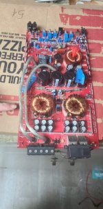
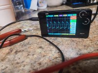
I have a skar sk 1500.1. At the time, this was my first amp. So I pulled the rectifiers to separate output from power side. I had recently changed out some bad power supply fets at first due to them being bad. After I changed them I powered everything up, and they immediately got hot once the protect light kicked on, and relay turned amp on. After I changed the driver transistors and fets once again. Boom. Same thing. Once I pulled the fets, I had good square waves on the oscope, all voltages for gate and source were the same. The issue is the second I put new fets in the board, I blow them. And the protect light doesn't even come on now. The relay does its job, everything looks good on the scope, until I put fets. Power supply is running at 13.8 volts and 1.5 amp limit.
When I do not have fets in, it runs at .15 amps. When they are in, it'll peg out at whatever I have it set at. The highest I've had it (forgot to check it) is 2.2 amps.
Can anyone lead me in the next direction on what to check? I have pictures of what I scoped with the fets out. And a picture of the side that goes out once I put them in.
Attachments

Re-check the drive waveforms with a loading capacitor.
Use a capacitor of 0.1-0.01uf connected between the gate and source legs. check all FET locations. All should look the same. Post a photo of one of the waveforms.
Use a capacitor of 0.1-0.01uf connected between the gate and source legs. check all FET locations. All should look the same. Post a photo of one of the waveforms.
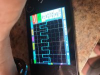
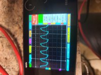
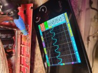
I don't know ... this thing is nuts. I got 4 different waves.... im just done with this one. It was my first one playing with it and learning. It did its job.... I used a .1 capacitor. As you said. Frustrated right now
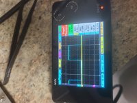
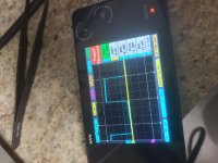
I'm not sure what #2 is showing. Deal with the other problems then come back to it.
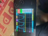
#4 is right.
For 1 and 3, you either have defective PNP driver transistors or a bad connection to ground on the collectors of the PNP driver transistors.
After finding the problem for 1 and 3, confirm that they look like #4 and re-check #2 to see if anything changed.
#4 is right.
For 1 and 3, you either have defective PNP driver transistors or a bad connection to ground on the collectors of the PNP driver transistors.
After finding the problem for 1 and 3, confirm that they look like #4 and re-check #2 to see if anything changed.
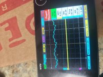
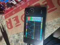
Here is another test with a change of pnp and npn transistors. The perfect square wave was before the capacitor test. I noticed a super high voltage rate.. 136 volts. I used a ceramic capacitor 104 as you mentioned again. All the wave forms were the same on two banks on the same side. The two banks on the opposite side were squiggly.
After the test, for ***** and gigs, I tested all the source and gates again. Got 16.8 volts, and all the square waves were not quite perfectly square.
After the test, for ***** and gigs, I tested all the source and gates again. Got 16.8 volts, and all the square waves were not quite perfectly square.
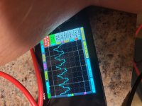
That's 13.6v. The scope thinks you have a 10x probe.
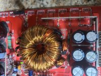
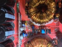
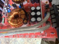
Post a good quality image of the PS section (closely cropped) that makes the PS section fill the display. Move the wires out of the way so I can read the circuit board designations for ALL of the PS FETs.
Post a good quality image of the PS section (closely cropped) that makes the PS section fill the display. Move the wires out of the way so I can read the circuit board designations for ALL of the PS FETs.
Ohh yeah..lol I forgot about the x10. Here are the pics. Tried the best I could. I noticed I wasn't getting voltage at my source pots at the fets after the testing. So I had to change the transistors again. Now it's back to normal.
Attachments

What source pad are you referring to? A driver or the PS FETs?
Are all of the gate resistors within tolerance?
Are all of the gate resistors within tolerance?
Wasn't getting it at ps fet source pads..I'll have to check the specs in the morn as I misplaced my print out on the transistors
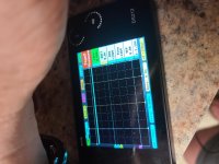
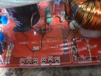
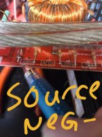
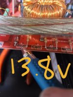
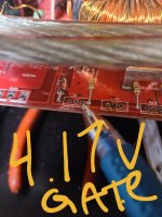
Ok just tested gate resistors. All but two read 47 ohms. The other two read 47.2/3. I rechecked my ps fet pins. However one resistor looks burnt enough to not see color rings. But it still reads fine. I was backwards. You are correct. My source is negative. From gate resistor pad I show a 4.1v reading and at the fet gate pad. Center pad of ps fets I get 13.6 when multi meter is grounded at ground terminal and red lead is touched on center. And source is ground. I posted a picture to show what I'm looking at.
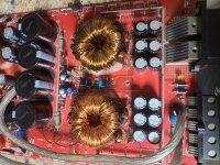
I did however find a source pad that doesn't meter. So I know it's not getting contact to ground.
I did however find a source pad that doesn't meter. So I know it's not getting contact to ground.
Attachments
Install the capacitor across the gate and source of Q11.
Connect the scope ground to main ground terminal. What is the signal on the gate pad of Q11?
Connect the scope ground to main ground terminal. What is the signal on the gate pad of Q11?
That's OK.
Do this for one transistor in each of the other 3 banks. If they all look like this, no need to post any more photos. If they do not, post a photo and include the circuit board designation for the FET location that's being tested.
Do this for one transistor in each of the other 3 banks. If they all look like this, no need to post any more photos. If they do not, post a photo and include the circuit board designation for the FET location that's being tested.
- Home
- General Interest
- Car Audio
- Skar sk1500 help