for example
a box witch 23 litre ,
a driver 7 inch and T/S parametre
Fs 31 hz
Re 5.6 ohm
qms 1.95
qes 0.32
sd 150
vas 42.7
xmax 6
70 w
19.8mms , 1.382 Rms , 8.12 Bl .
what are the advantages or disadvantages in use of larger or smaller ports to a given FB : 44hz for example .
ex 5 cm port diametre or 7 cm port !
in small port we have to avoid exceding 10% sound speed .
in large port ...????
and for this example what are your sugestion for FB and WHY ?
There's a lot to say and investigate. I would leave you with this. There's a software zip made by me attached, from the work of Notax@diyAudio in the port calculation, following is extensive experience. Hope you appreciate.😉
http://www.diyaudio.com/forums/multi-way/120887-port-calculations.html
http://www.diyaudio.com/forums/multi-way/120887-port-calculations.html
Last edited:
thanks
but for the given driver witch that T/S parametre and a volum of 23 L , what FB and port size you chose ?
and for a given FB 44HZ = diametre port size ?
i ask because i made some simultation in some program and
for a 7cm dia , and 21cm length - FB is 44 - F3 41hz -
port air speed 26m/s at 43hz
port rezonance at 681hz witch 2db pick .
if i choose a smoller port 5cm witch 10cm lenght - same FB and F3
port air speed is 52m/s at 43hz
but the port resonance is better and no pick is seen
thanks
but for the given driver witch that T/S parametre and a volum of 23 L , what FB and port size you chose ?
I would do ~40Hz with a 7cm port, sim attached.
Attachments
thanks
but for the given driver witch that T/S parametre and a volum of 23 L , what FB and port size you chose ?
and for a given FB 44HZ = diametre port size ?
i ask because i made some simultation in some program and
for a 7cm dia , and 21cm length - FB is 44 - F3 41hz -
port air speed 26m/s at 43hz
port rezonance at 681hz witch 2db pick .
if i choose a smoller port 5cm witch 10cm lenght - same FB and F3
port air speed is 52m/s at 43hz
but the port resonance is better and no pick is seen
Did you use the formula already (.zip)?
It gives 53.1mm min. as you can see from it, with Ron E Fb~40Hz.
Attachments
Ron E thanks for the sim
Inductor yes i use the formula .
nobody knows the advantage or d - in using of a large vs small port ?
from my sim look like this .
small port have lower GROUP DELAY ( smoother : phase response , sistem impedance and cone displacement .
large port have higher maximul acoustic power on low fr , lower cone displacement on FB fr ,
for disadvantage they have higher group delay .
and effect of port resonance greatly amplified .
Has anyone knowledge -- for port position - on bottom of the speaker what benefits arise or vice versa ?
Last edited:
This is only because a smaller cross sectional area port is further from an "ideal" port due to increased turbulence. Increased turbulence means more losses, so the box (Helmholtz resonance) Q becomes slightly lower than a larger port that more closely approaches "ideal" performance.Ron E thanks for the sim
Inductor yes i use the formula .
nobody knows the advantage or d - in using of a large vs small port ?
from my sim look like this .
small port have lower GROUP DELAY ( smoother : phase response , sistem impedance and cone displacement .
The same can be "achieved" with the larger port by adding a small amount of additional losses in the box in the form of extra lining. I say "achieved" because it's not something you want to achieve, as either an undersized port or an excessively lossy box move you further away from the maximum theoretically attainable cut-off frequency/efficiency for a given size box.
If the box Q is too high to get the alignment you want then instead of increasing port or box losses you should be reducing the volume of the box - same effect on the alignment, smaller box. Of course a practical box (unless it's a sub-woofer) will need at least some lining on the walls for higher frequency isolation and absorption, the effect of which is you need a slightly larger box than predicted to get the same response alignment.
In other words, the difference you note in group delay, impedance curve and so on are related to the difference in box Q, not purely to large port vs small port - the port size is just one thing you can change that has an effect on the box Q. (And only a relatively small effect compared to some other things)
Also, don't get hung up on the simulated impedance curve being "smoother" in one configuration or the other - of all the measurements that matter about a speaker, the impedance curve through the bass resonance region is almost inconsequential in how a speaker sounds.
It's useful to look at to see if the box is tuned where you think it is, (dip between the two peaks) whether there is unexplained leakage in the box (lowering the maximum impedance peaks, but you can only really tell this if you have another box to compare with) and to see what minimum and maximum impedance the amplifier will be subjected to, but beyond that it tells you nothing of particular interest, and no one shape of impedance curve is inherently better or worse...
There's more than that though. It's not just a matter of higher maximum SPL. A port that is too small in cross sectional area will start to cause dynamic range compression and increased harmonic distortion near the box resonant frequency well before there is audible "chuffing" noise from the turbulence.large port have higher maximul acoustic power on low fr , lower cone displacement on FB fr ,
This is because past a certain point increases in velocity causing turbulence will start to lower the box Q, resulting in less output near the tuned frequency, and less loading on the driver - so cone excursion will be greater than anticipated, so will distortion, while SPL will be less than anticipated.
With a small port area for a given box/driver the driver will rapidly start to become "unloaded" as it's driven harder and harder - the port will cease to function as a useful resonant loading device, and the driver will start to act like it's operating in a leaky sealed box, so it's very important that this can't happen within the drive/excursion limits of the driver.
The often quoted 17m/s safe limit for port air velocity is the point at which typical non-tapered ports start to emit audible chuffing noises, but compression, distortion, and reduction in loading can start to occur significantly below this.
I don't think it's correct to characterise this as a disadvantage - as far as I know the larger port size is - all other things being equal - simply shifting the alignment slightly (by increasing box Q) to one that has a sharper cut-off and therefore higher group delay. However if you re-align the alignment (for example by making the box slightly smaller) you should end up with the same group delay but with the larger port - worse group delay is not inevitable with a larger port, it's just a function of the total alignment.for disadvantage they have higher group delay .
Not sure what you mean by this ? Are you referring to high frequency (midrange) pipe mode resonances ? If so, pipe resonances are worst when a pipe is narrow relative to its length - because all possible reflection angles within the pipe result in very little change in path length - so you get a narrow high Q resonance. A fat pipe of the same length will have less resonance since there is more variation in path length for different angle reflections.and effect of port resonance greatly amplified .
On the other hand when you increase port area the length grows faster than the diameter to keep the same tuning so in that sense the resonance becomes worse, but the more important factor is the frequency of the resonance gets lower.
Too long a pipe may push the pipe resonance down into the region where the driver is operating, resulting in spurious high frequency output from the port near its self resonance, and this is something that needs to be considered when deciding on length/diameter. I would point out that this problem is inevitable in a 2 way bass reflex design, and a good reason to put the port on the back instead of the front...
In general I think it's preferable to err on the side of the port area being bigger than you think it needs to be, that's the "safe" mistake to make, provided that it doesn't result in such a long port that putting it in the box becomes problematic, or that the pipe resonances aren't put at an inconvenient frequency.
Also you have to consider that any volume consumed by the ports no longer exists as cabinet volume - thus requiring an increase in box volume. For a small box tuned to a low frequency large diameter ports quickly become impossible as the ports consume an inordinate percentage of the box volume 😛
Bottom as in bottom of the front panel, or actually underneath with a gap ? The ports on most speakers are tuned below 60Hz, and this is low enough in frequency that vertical room modes don't really come into play, but there will still be some boundary gain as the port gets closer to the floor.Has anyone knowledge -- for port position - on bottom of the speaker what benefits arise or vice versa ?
So measured at the listening position a port near the bottom of the front panel will have an apparent increase in output compared to one at the top of the front panel on the order of 1-2dB. (Obviously depending on the size of the cabinet etc)
Because this increase in response is only occuring for the component of the bass coming from the port, this will shift the apparent bass alignment. If it's an alignment with a small box where the port is tuned at say the -6dB point, this might be beneficial, giving you a slight improvement in F3 for "free", but without causing peaking.
On the other hand if you had a critical B4 alignment where the port is tuned to the -3dB point the apparent increase in port output relative to the driver may push the alignment in the direction of peaking...
I think a more interesting question is whether the ports should go on the front or the back of the speaker. It's a whole discussion of it's own, and whilst there are some cases where ports on the front are necessary (small speaker designed to position against a wall etc) in general I think there are a lot of advantages from putting them on the back - the biggest one is preventing the majority of the midrange leakage occurring near the pipe resonance from reaching the listener...
If the back of the speaker is less than half a metre of so from the front wall a rear port will also receive additional boundary gain, much like placing it near the floor - which, again, may or may not be beneficial depending on the alignment...
Last edited:

DBMandrake very very useful details
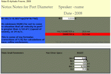
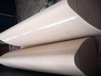
to be more precise i will put some picture with the project in question .
for driver - Usher 8948A and 9950-20 .
internal volume without driver , filtre and port is 25.6 L
final volume is 22-22.5 L.
for the port i mean "underneath"
i could try on back or front ! but underneath is easier and port size is a problem
and for FB i thought is ok a 42hz - 65mm - or 70mm diametre /
internal volume may be reduce if necessary later
offtopic grooves in the MDF were filled with resin fiber
Attachments
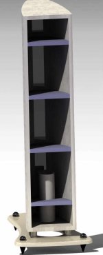
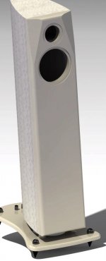
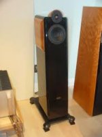
I don't see a problem with the location of your port at the bottom of the cabinet. In fact with that cabinet shape it's your only practical choice.
Judging by the first photo you have plenty of gap between the entrance of the port and the floor, as well as clearance around and through the supporting base plate, provided the base plate is a permanent fixture, and the spiked feet can't be removed.
(With the stand resting directly on the floor without the feet there would be insufficient clear airflow through the gap between the baseplate and bottom edge of the cabinet, IMHO)
The effect of the port exiting near the floor will be both a slight increase in the relative output of the port due to boundary gain (as described in my previous post) as well as the box tuning being slightly lowered in frequency due to mass loading from the floor, however at that distance the change would be small.
Box tunings never quite come out right at exactly the tube length predicted anyway, since T/S simulators don't model the exact shape and dimensions of a box, treating the system as lumped components, so you always need to adjust the length of the port somewhat to get the tuning at the desired frequency. (Make sure you leave room in the design to change the length of the port +/-20 % around predicted length during the tuning process)
As for whether 65-70mm diameter is enough, that really depends on the output ability of the driver, and I'm not familiar with that driver. Assuming you have a full set of T/S and mechanical parameters for it I would suggest modelling it in WinISD Pro (freely available) and take this approach:
Enter driver parameters, box volume and desired box tuning frequency, set port diameter to 65mm to begin with. Check the transfer function magnitude shows the expected frequency response. (Just in case there are errors in data entry if you're not previously familiar with WinISD Pro)
Look at the "Maximum SPL" curve, this will show maximum output ability of the driver/box combination limited by both power handling and cone excursion. Look at the area ~ +/- 5Hz of the box tuned frequency to find the maximum SPL that can be produced near the box tuning, and make note of this.
Switch to the SPL graph, and in the signal tab of the project increase "System Input Power" until the indicated SPL at the box tuned frequency equals the maximum value previously noted.
Now switch the graph to "Rear Port air velocity", this will show a graph of air velocity at this input power level. Because power handling is maximum at the box tuned frequency, this is close to a worst case scenario.
Check that the peak velocity is below ~17m/s. If not you can now play with the vent diameter on the Vents tab of the project and see the effect on air velocity at the same power level, it will also calculate the required increase in port length.
(Note, due to a bug in the program, sometimes changing port diameter causes the box tuning frequency on the box tab to be reset to 0 - you need to re-enter this after changing the port diameter)
I'll give an example of a box I have - an 8" full range driver (165mm cone diameter) with an xmax of about 3mm, and Pe of 35w in a 45 litre box tuned to 43Hz.
Following the above method, maximum SPL at 43Hz is 102dB (1 metre) and it's found that 30w is taken to produce it. (although the driver is 94dB sensitivity, 43Hz is the -6dB response point)
Initially I had a single 75mm diameter port, approx 100mm long.
With power input set to 30w, the maximum air velocity is 18.5m/s at 30Hz, and about 15m/s at 43Hz. Note: 30w at 30Hz is actually well beyond the drivers excursion limit (since air velocity peaks lower in frequency than port tuning in most cases) so it's quite a harsh and conservative estimation.
In listening tests (before I even simulated it) it was apparent there was quite audible distortion in the bass at moderately high volume levels from 40-80Hz, as well as audible "chuffing" from the port with a loud tone near the box tuning. This agrees well with the rule of thumb of not getting too close to 17m/s.
In the end I decided to go with two 75mm ports (now ~230mm long to reach the same tuning frequency) to double cross sectional area. In the simulation this reduces maximum port velocity to 9.5m/s, and in listening tests port chuffing was gone even at high levels, and the obviously audible distortion in the bass below the xmax limit is also gone, in fact bass notes are very clean for such an old driver. Dynamic performance in the bass was noticeably improved.
So in this particular design 18m/s maximum was audibly poor, while 9.5m/s sounds fine. Somewhere in between was the dividing line.
Of course in your design you only have room for one port but a small increase in diameter will make a larger increase in the area, and it's the area that matters. Because your cabinet volume is half the example I gave, it's possible that you may not be able to make a sufficiently large/long port without consuming too much internal volume, so you may have to accept that the drivers maximum output potential might not be reached with the size of port that is practical. (In other words distortion and port noise at high outputs will be worse than what the driver is capable of)
Hope that helps 🙂
Last edited:
i made some print screen with simulation in bassbox ,unibox and winisd
there are some big differences , one to another .
in bassbox for example even F3 is change after changing port area and let the same FB . 40HZ .
Bassbox Air vent velocity is much smaller then winisd including the vent resonance peak !
group delay and cone displacement is lower .
Maximum port size in bass box is 8.2cm - bigger then that - length is written in red for warning .
how much resonance pick influence sound quality ?
(Attachments removed at members request)
usher be-718 have the same driver - use 15-16 L 47FB , 13cm*1cm area port
but usher mini dancer 1 have the same driver - unknown volume , port area 17.5 *2.5 cm -
regardless of simulations made can not be that big !
what may be the explanation ?
but usher mini dancer 1 have the same driver - unknown volume , port area 17.5 *2.5 cm -
regardless of simulations made can not be that big !
what may be the explanation ?
Good point. Probably not enough. (and/or) Less exposure to the back of the cone, or less power (as Simon said). Port area of the second is more than 3 times bigger (D=7.46cm) the first one, so that is ok.usher be-718 have the same driver - use 15-16 L 47FB , 13cm*1cm area port
but usher mini dancer 1 have the same driver - unknown volume , port area 17.5 *2.5 cm -
regardless of simulations made can not be that big !
what may be the explanation ?
Last edited:
i decided to use a 72mm with 260mm long port
fb ultimately may be from to 38-44hz
I saw some suggestions that sim. programs shows greater lenghts than apparent from mesurements .
fb ultimately may be from to 38-44hz
I saw some suggestions that sim. programs shows greater lenghts than apparent from mesurements .
back to usher speaker
model USHER - using 8945A
CP-6311 have 7.5cm diameter with 13cm length .
CP-730 have exactly the same port size .7.5 - 13 lenght
usher mini dancer (using 8948A) have 17.5*2.5 cm area witch 13cm length (which is similar is size wich previous models)
i brought this tree model in discussion because - port size suggests that have large enclosures - between 28 and 35 litres and FB 45-52 hz ! .
does not seem strange to use such a large volume ?
far exceeds x-max - and have big group delay .
what volume seems most appropriate for this driver ?
my enclosure may have internal volume between 22 and 28 Litre - difference cam be filled with sand .
i was thinking to use a port that may be adjusted later - 7.5cm - 20cm long =- wich possibility to introducing inside it - another port wich 7.5cm on exterior and 7.1cm interior - and length depending on mesurements .
what suggestion , opinions ... can give me .
Attachments
- Status
- Not open for further replies.
- Home
- Loudspeakers
- Multi-Way
- Size of port ? thin or thick ? advantage ,disadvantages FB