This is somewhat of a different area of endeavor for me; usually I tend to concentrate on tube based signal paths.
Some months ago I decided that I would work on a simple low distortion AC source for use with the plethora of cheap chip amps available on eBay. My thoughts were I would use LM3886 to drive an EI step up transformer to provide clean sine wave power at 100V - 120V or 220V - 240V at 50 or 60Hz to power a couple of turntables I have. More specifically I was interested in having some fun and running a 50Hz platter equipped Garrard 401. Figured rather than just do a 50Hz platter strobe, why not do a whole supply, given the claims made by those using fancy expensive supplies on their turntables.
This is a work in progress.. My initial efforts with an off the shelf PIC based 50Hz source disappointed me in that the frequency was 0.06% low. I felt I could do better than this.
The original design comprised regulators and a sixth order Sallen-Key based VCVS to convert the square wave from the source into a clean sine wave.
Subsequently I designed my own square wave source which had the added benefit of costing less and supporting the generation of both 50Hz and 60Hz with an order of magnitude better frequency precision.
All of the parts are cheap and readily available.
I laid out the original project in Altium, but in a story too long to share here no longer have access to a license. The additional board was hand built p2p on vector board.
I will post the schematics and more detail in the next post, this one is getting a bit long... 😀
Attachments

Currently what I have is built on a number of PCB I laid out and a hand built prototype of the oscillator/source.
I have yet to cross the bridge of marrying the oscillator and LPF board with any sort of power amp and step up transformer.
I have a chassis box on the way from China, and am waiting for Antek to have more stock on their 100VA 15V toroid for the raw supply. The step up I will be using is a universal type from Triad UPL10-5000 which is a 10V/5A type with dual primaries which I can wire in series for 240V output if desired.
Others who have blazed this trail cautioned against toroids due to the possibility of saturation and the effect on the power amplifier if that happens. I plan to use a fairly aggressive zobel across the output of the amp on the order of a a couple of uF in series with a 2.7 - 4 ohm power resistor, this should help with inductive loads..
I caution that I have not tried to make high voltage AC yet, and may run into some very odd issues, and including exploding LM3886TF..
Oscillator:
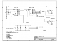
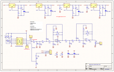
Anyway referring to the oscillator schematic (KiCad), the binary counter used, a 74HC4060 incorporates a competent crystal oscillator. I chose to use a 2.4576MHz crystal to reduce radiation of harmonics resulting from the use of a higher frequency crystal, and because this frequency subjected to binary division results in a value friendly to simple further division by a 74HC4017Johnson counter. I chose a divisor of 4096 which results in an output frequency of 600Hz, a further division by 5 or 6 results in 120Hz or 100Hz respectively, and a final division by 2 via a D flip-flop gives you a duty cycle of 50% and 60Hz or 50Hz with a single crystal, three cheap chips, a few caps, and a couple of headers for configuration are it.. Not elegant, but functional. I probably should not have used 74HC series parts due an amplitude asymmetry that results in DC offset at the output of the filter. (It can be nulled.) I have not yet evaluated 4000 series CMOS equivalents, but they may work better, the 74HC74 would have to be replaced with a 4013 requiring some minor changes, but the 4060 and 4017 slot right in for the 74HC series parts or would had I had sockets on hand.. LOL
LPF Filter:
This was also surprisingly cheap compared to through hole switched capacitor filters and performs more than adequately, note that it was really designed for 50Hz, but I have not retuned it for 60Hz (there is such a version) as this would degrade the 50Hz performance substantially.. The filter is about -3dB at 60Hz compared to 50Hz a compromise I am happy to live with, and the current filter is down more than 50dB at 150Hz relative to 50Hz, and is even better at 180Hz when outputting 60Hz.
The filter is two cascaded 3rd order moderately high Q LPF filters, Q is ~2.2, no attempt has been made to be clever or to optimize anything other than stop band attenuation - it's not necessary for this application.
Bipolar power is used in order to try and minimize power up LF transients that might trip the amplifier protection circuit when driving a transformer. (Transformer behavior when confronted with DC) The jury is out on how effective that might be. Long mute period may be needed, or even ramping up the drive signal to the amplifier.. To be seen I guess.
I have yet to cross the bridge of marrying the oscillator and LPF board with any sort of power amp and step up transformer.
I have a chassis box on the way from China, and am waiting for Antek to have more stock on their 100VA 15V toroid for the raw supply. The step up I will be using is a universal type from Triad UPL10-5000 which is a 10V/5A type with dual primaries which I can wire in series for 240V output if desired.
Others who have blazed this trail cautioned against toroids due to the possibility of saturation and the effect on the power amplifier if that happens. I plan to use a fairly aggressive zobel across the output of the amp on the order of a a couple of uF in series with a 2.7 - 4 ohm power resistor, this should help with inductive loads..
I caution that I have not tried to make high voltage AC yet, and may run into some very odd issues, and including exploding LM3886TF..
Oscillator:
Anyway referring to the oscillator schematic (KiCad), the binary counter used, a 74HC4060 incorporates a competent crystal oscillator. I chose to use a 2.4576MHz crystal to reduce radiation of harmonics resulting from the use of a higher frequency crystal, and because this frequency subjected to binary division results in a value friendly to simple further division by a 74HC4017Johnson counter. I chose a divisor of 4096 which results in an output frequency of 600Hz, a further division by 5 or 6 results in 120Hz or 100Hz respectively, and a final division by 2 via a D flip-flop gives you a duty cycle of 50% and 60Hz or 50Hz with a single crystal, three cheap chips, a few caps, and a couple of headers for configuration are it.. Not elegant, but functional. I probably should not have used 74HC series parts due an amplitude asymmetry that results in DC offset at the output of the filter. (It can be nulled.) I have not yet evaluated 4000 series CMOS equivalents, but they may work better, the 74HC74 would have to be replaced with a 4013 requiring some minor changes, but the 4060 and 4017 slot right in for the 74HC series parts or would had I had sockets on hand.. LOL
LPF Filter:
This was also surprisingly cheap compared to through hole switched capacitor filters and performs more than adequately, note that it was really designed for 50Hz, but I have not retuned it for 60Hz (there is such a version) as this would degrade the 50Hz performance substantially.. The filter is about -3dB at 60Hz compared to 50Hz a compromise I am happy to live with, and the current filter is down more than 50dB at 150Hz relative to 50Hz, and is even better at 180Hz when outputting 60Hz.
The filter is two cascaded 3rd order moderately high Q LPF filters, Q is ~2.2, no attempt has been made to be clever or to optimize anything other than stop band attenuation - it's not necessary for this application.
Bipolar power is used in order to try and minimize power up LF transients that might trip the amplifier protection circuit when driving a transformer. (Transformer behavior when confronted with DC) The jury is out on how effective that might be. Long mute period may be needed, or even ramping up the drive signal to the amplifier.. To be seen I guess.
Attachments
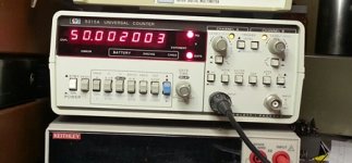
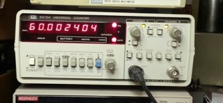
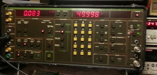
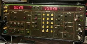
Some basic measurements..
For frequency related measurements refer to the HP counter as it is more accurate than the Amber frequency counter.
THD measurements are done with the 30kHz LPF engaged. (No significant difference without it) Measurement set is an Amber 5500 with the high performance pack.. (LOL)
For frequency related measurements refer to the HP counter as it is more accurate than the Amber frequency counter.
THD measurements are done with the 30kHz LPF engaged. (No significant difference without it) Measurement set is an Amber 5500 with the high performance pack.. (LOL)
Attachments
Note this could power other things depending on your willingness to invest in bigger power amps and transformers. (200W linear amps are available on eBay)
Class D might be an option as well.
Class D might be an option as well.
How do these motors work exactly? Is it like a PSC with a toothed rotor or something? Maybe a driver amp capable of good low supply voltage behavior would allow a soft start and shutdown implemented on the output supply level (safeguard) in addition to some gain or volume control tracking supply voltage to keep the drive sinusoidal and play nice with any transformer, through the ramp periods and even line loss. Not trying to be distracting. Just some thoughts.
Specifically targeting shaded pole induction motors like those used in TD-124, and Garrard 301/401. There are countless others..
I don't expect the transformer/amplifier problems to be insurmountable.
What surprises me is that the circuitry is not complex nor expensive, I guess it is the specialization that makes the few commercial (and nameless) options so ridiculously expensive, admittedly they are probably also a lot more sophisticated than this one.
A plain induction motor with squirrel cage rotor would develop some minimum slip just with unloaded rotor losses. That would mean available line frequency and voltage would almost never be exactly what is needed to establish a particular platter speed. I guess some AC synchronous motors employ permanent magnets. For the lack of cogging I can see why tweaking the drive to an induction motor would be worthwhile, even if complicated.
Last edited:
The induction motors used in turntables have a pretty predictable velocity/torque curve based on line frequency, voltage and load. Because they pole slip but don't loose lock with the line varying the load on them deliberately allows them to run over a range of speeds - this is how the speed on a TD-124 or Garrard 301/401 can be adjusted using an eddy current brake. Speed is very consistent if voltage and load are as expected.
I have seen a few very inexpensive synchronous motors that used ring magnets attached to the rotor. Over time they usually fall off and since they are not marked for balance once this happens it is a devil of a job to get the motor to run smoothly again. Garrard as one example made this type of synchronous motor after inexpensive Japanese turntables appeared on the scene. (I believe BSR may have too, but most of their inexpensive changers seemed to have had two pole induction motors)
I have seen a few very inexpensive synchronous motors that used ring magnets attached to the rotor. Over time they usually fall off and since they are not marked for balance once this happens it is a devil of a job to get the motor to run smoothly again. Garrard as one example made this type of synchronous motor after inexpensive Japanese turntables appeared on the scene. (I believe BSR may have too, but most of their inexpensive changers seemed to have had two pole induction motors)
So I guess since any sort of meshed transmission is out for noise and vibration, no matter what kind of motor, slip at some point is inevitable, and all systems except direct drive employ "overdrive" in the ratio (for tables with speed adjust), since faster than synchronous speed is impossible? My question then is specific motor frequency to the nines a little unimportant so long as it is quite stable?
Last edited:
I think that such a system could benefit from a fine-tuning vernier: it could be used to compensate for various sources of inaccuracies in the slip percentage and mechanical transmission for example.
I have already examined the possibility of such a vernier on a digital generation chain (for other purposes but the principles remain identical).
Basically, I see two promising paths, both based on the offset-PLL principle: one rather conventional, except the frequency subtractor and phase comparator would be digital, and the other using a V/F converter to servo the difference frequency to an analogue voltage.
Both options would give a convenient, deterministic and accurate means of varying the output frequency, by say +/-0.5% full range.
I will try to come up with such an add-on circuit when I find some time (and inspiration)
This circuit was intended originally to provide power for a 50Hz TT that I want to keep stock. Sort of plug it in and forget about it. The stock speed adjustment would be used as designed, that said I have a 3 phase Papst Aussenlaufer motor that is going in one of the 124s and that will be controlled by a Mark Kelly controller which is variable frequency - I can adjust the frequency to get the table to run on speed without the brake..
To Andrew's comment the drive ratio with an induction motor is set several % high and the eddy current brake is used to slow it down to nominal speed or slower as needed. Properly set up it is predictable and repeatable. Speed is stable, frequency is the primary determinant (about 90%) with voltage and load being the other two factors. The strobe does obviously expect to see nominal line frequency otherwise the speed indication will be incorrect.
To Andrew's comment the drive ratio with an induction motor is set several % high and the eddy current brake is used to slow it down to nominal speed or slower as needed. Properly set up it is predictable and repeatable. Speed is stable, frequency is the primary determinant (about 90%) with voltage and load being the other two factors. The strobe does obviously expect to see nominal line frequency otherwise the speed indication will be incorrect.
Well nuts, I just got a 50 Hz strobe board sorted out and ready to install in my 401.
This project looks very interesting, Kevin, but probably over my head, so I'll check in from time to time.
Thanks for the thread.
This project looks very interesting, Kevin, but probably over my head, so I'll check in from time to time.
Thanks for the thread.
Doug, that was my plan too, but in the end I followed this path out of curiosity. Eventually I may get it together and layout a full board with all of the circuitry required except the power amp. Need to master KiCad and that is going to take some time.
It's surprisingly simple and inexpensive to implement, the boards and the ELM chip I am no longer using actually cost more than pretty much everything else combined.
It's surprisingly simple and inexpensive to implement, the boards and the ELM chip I am no longer using actually cost more than pretty much everything else combined.
Kevin
I am intrigued that you got the LM3866 to work in this application, I've never been able to get it, or any of that class of chip amp, to work reliably running a Garrard motor. On my several attempts they've started out looking good and then developed an intemittent problem where they simply refused to start.
I wonder what you are doing that I didn't?
Last edited:
Gary Galo did this in Audio Amateur 1/86 using an oscillator driving a Hytronics amp module driving a toroid backwards to power the motor.
My Simon Yorke S4 turntable(sorry Simon RECORD player) uses the exact same type of circuit. I'm quite sure many others have done the same thing. The S4 runs the motor at 90v for reduced cogging.
I am working on doing the exact same thing, oscillator driving a LM3886 driving a toroid backwards. With so many companies using toroid's reliably. I can't see why it is an issue.
Kevin
I am intrigued that you got the LM3866 to work in this application, I've never been able to get it, or any of that class of chip amp, to work reliably running a Garrard motor. On my several attempts they've started out looking good and then developed an intemittent problem where they simply refused to start.
I wonder what you are doing that I didn't?
We'll see how successful I am, I am concerned about the robustness of the LM3886 and have not done any real testing to this point. My strategy is to use pretty heavy snubbing and to run it at relatively high output voltage and relatively low current with a VS just a few volts beyond what is required. (Thinking of SOA, minimizing VCE at high load currents) I most likely will ramp the drive to the amp over a couple of hundred ms - will try without first. Worst case I will go for a hybrid design I have used out to a 1kW in the past that is if I can still get the transistors required. Fingers crossed on this one, I've got a lot to learn I suspect.
Gary Galo did this in Audio Amateur 1/86 using an oscillator driving a Hytronics amp module driving a toroid backwards to power the motor.
My Simon Yorke S4 turntable(sorry Simon RECORD player) uses the exact same type of circuit. I'm quite sure many others have done the same thing. The S4 runs the motor at 90v for reduced cogging.
I am working on doing the exact same thing, oscillator driving a LM3886 driving a toroid backwards. With so many companies using toroid's reliably. I can't see why it is an issue.
I too would have thought that a toroid would be ideal and indeed used one with a 1kW set up using a Bose 1800 power amplifier 15yrs ago, no problems.. Others using chip amps and running 15 - 20W motors have warned me that the lossier EI transformer results in fewer problems with chip amps like the LM3886. I am still learning, far from having it all figured out and took this advice on faith based on who it came from.
Worst case I will parallel a couple of LM3886 which might do the trick. Even more worse case I will design something to do the job. I guess I will find out shortly.
I've gone to some lengths to minimize bad near DC behavior during start up, but now have no access to a DSO I might have used to look at the first few hundred ms of operation to see how it behaves. Maybe next year I will buy one of those nice inexpensive Tek TBS series scopes..
I expect I may have to modify those cheap amp boards to incorporate a reasonable mute delay.
Yeah, been there done that.
I find snubbing on the secondary side of the trafo is optimal. To make it universal I use trafos with dual secondaries which are parallelled for 115V and in series for 230V.
I then put the Boucherot cell across one "half secondary". I tried a bunch of different values, calculated the highest and lowest time constants that gave good results and took the geometric mean of these values (geometric mean = nth root of the product of n values).
I've settled on a 2 uF cap in series with a 470 ohm resistor. I use a 440V rated polypropylene film motor run cap and a Vishay RCH50 resistor (pdf here) : IMO you don't want a wirewound here.
After a lot of futzing with the various solid state solutions, including using a 300 Watt amp based on the IRS2092 chip I still had the intermittent non-start problem, so I gave up on SS for this. I'm beginning to suspect that it was actually the power supply for the various amps that was the problem.
If you get something to work I'm all ears as I have about $6,000 worth of parts and custom wound transformers here from various attempts at this, I'd love to be able to get rid of them.
In contrast to the troubles I had with solid state, push pull 300Bs (or KT88s in triode) work perfectly every time, so that's what I do now.
Cool, given my propensity for tubes that is what I should be doing too.. Keep your fingers crossed. 😀
Supplies are linear, bipolar, just bridge and capacitors - should provide plenty of energy to explode a chip amp here or there.. 😱
😱
Supplies are linear, bipolar, just bridge and capacitors - should provide plenty of energy to explode a chip amp here or there..
😱- Status
- Not open for further replies.
- Home
- Source & Line
- Analogue Source
- Single Phase Power Source (AC Regenerator) for Induction Motor Powered Turntables