Any ideas on simulation software to use to calculate response from a sub placed in a corner? I'm looking at designing a dual 10" closed box design like the Steinway Lyngdorf S-210. I have several woofers identified, but I would like to understand what the interaction with room looks like before settling on a particular model.
Hi,
For hifi corner placement is bad, for AV not so much.
You'd be better off with two boxes with an amp in one. Place
~ 1/3 along the back wall and ~ 1/3 along opposite side wall.
rgds, sreten.
For hifi corner placement is bad, for AV not so much.
You'd be better off with two boxes with an amp in one. Place
~ 1/3 along the back wall and ~ 1/3 along opposite side wall.
rgds, sreten.
I have heard the Steinway lyngdorf system with two corner woofers and a set of small main speakers, and I was blown away by the fact that the bass was super tight and I could swear that it was coming from the small main speakers (note a DSP was used for xover, frequency flattening and time alignment of bass and main speakers).
https://steinwaylyngdorf.com/technology-and-innovation/boundary-woofer
While marketing material like this needs to be taken with a large dose of salt, there is something intuitively right about getting direct and first reflections aligned, coupled with the capability to level out the room nodes in the DSP.
Now back to the question, do you know of any loudspeaker box simulation packages that can simulate the frequency from box dimensions and the room effects you would get from box placement?
Hi,
If you use a DSP to do all those things, simulation doesn't really matter.
No box simulation package takes into account room dimensions and placement.
rgds, sreten.
If you use a DSP to do all those things, simulation doesn't really matter.
No box simulation package takes into account room dimensions and placement.
rgds, sreten.
While DSP can help you, it is generally speaking a very good idea to have the best possible starting point before you fire up your EQ 🙂
What I would like to explore is the following: I'm going for a relatively small closed box, 40-50l, two (high BxL) 10" woofer mounted in opposing fashion (one on each side of the box) to cancel vibration.
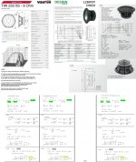
I could go with a stiff heavy cone like the Seas L26 Roy (mms=107g/fs=22Hz/Qts=0.31/Vas=87l/BxL=12) and get relatively deep bass, or with a lighter cone TIW250XS (mms=49g/fs=33Hz/Qts=0.33/Vas=66l/BxL=13)
The trade-off will thus be low fs or low mms. I conjecture that low fs is less important with corner placement due to room gain, but getting a highish xover point in 200-300 range that integrates well with main speakers would work best with a low mms cone and a damped box alignment (low box Q).
Would have been nice to explore in simulation that low range output would be adequate from low mms driver.
What I would like to explore is the following: I'm going for a relatively small closed box, 40-50l, two (high BxL) 10" woofer mounted in opposing fashion (one on each side of the box) to cancel vibration.
I could go with a stiff heavy cone like the Seas L26 Roy (mms=107g/fs=22Hz/Qts=0.31/Vas=87l/BxL=12) and get relatively deep bass, or with a lighter cone TIW250XS (mms=49g/fs=33Hz/Qts=0.33/Vas=66l/BxL=13)
The trade-off will thus be low fs or low mms. I conjecture that low fs is less important with corner placement due to room gain, but getting a highish xover point in 200-300 range that integrates well with main speakers would work best with a low mms cone and a damped box alignment (low box Q).
Would have been nice to explore in simulation that low range output would be adequate from low mms driver.

Impressive a lot of info - I'm surprised by the high f3 for seas in closed box, are you sure that the T/S Paramus are right (maybe fs is off?) ?
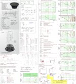
Any guesses as to who produces this woofer (what OEM)
https://steinwaylyngdorf.com/images/news/2014/time-domain-drivers/10-in-Woofer_710.jpg
Sorry my iPad browser crashes every time I use the inser hyperlink feature in editor
https://steinwaylyngdorf.com/images/news/2014/time-domain-drivers/10-in-Woofer_710.jpg
Sorry my iPad browser crashes every time I use the inser hyperlink feature in editor
Hi,
Room gain occurs for all placements, corner placement
exacerbates the room modes, and is generally only
good for maximising the limited output of an AV sub.
rgds, sreten.
Room gain occurs for all placements, corner placement
exacerbates the room modes, and is generally only
good for maximising the limited output of an AV sub.
rgds, sreten.
A premise for making corner placement work is dsp and time delay of main speakers, when dialed in, it is hands down the most impressive stereo bass I have experienced.
We are all entitled to our own opinions, but in this rare case I do not agree with you sreten 🙂
We are all entitled to our own opinions, but in this rare case I do not agree with you sreten 🙂
Impressive a lot of info - I'm surprised by the high f3 for seas in closed box, are you sure that the T/S Paramus are right (maybe fs is off?) ?
Hi cph2000,
Correct! .. fs should be 22 Hz rather than the in Mathcad the entered 33Hz😱.
b🙂
Attachments
At long last, we did some redecorating of the music room a few months ago. So with accessible space, I was able to test my 1955 AR1 sub in 14 positions forming a U along the working end of the room with the usual REW runs.
Can't say as I have any brilliant findings except that you'd be surprised how the low end FR fluctuates with speaker location. If I had any generalization for my room, it would be that the generally accepted rule of 1/3 usually does the most good for most room modes, sort of, for that speaker and room.
Big effect of opening the sliding door on the clothes closet on axis at the far end.
Build it and then test locations and then use DSP. Can't go wrong with a sealed box.
Ben
As Sreten said in the above #9, the corner placement is really only useful for maxamising volume and the resultant increase of peaks & dips in the room are much more difficult to level out - the peaks can be reduced okay with the dsp but not so easy to fill in the dips without signal degredation
As you are about to build your subs, suggest you have a look at the work of Floyd Toole (Harmon) and the well established development of multiple subs - James Romeyn also, and quite a few others, have developed fairly simple systems based on the multiple sub bass drivers (3 or 4) in the room - the dsp is part of the package and enhances the result
As you are about to build your subs, suggest you have a look at the work of Floyd Toole (Harmon) and the well established development of multiple subs - James Romeyn also, and quite a few others, have developed fairly simple systems based on the multiple sub bass drivers (3 or 4) in the room - the dsp is part of the package and enhances the result
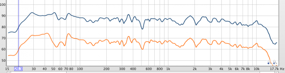
Here are curves with the closet door slid open and slid closed, left channel, driver about 1/3 across speaker-end wall. Curve south of 90 Hz a whole lot better. BTW, that's a 15-inch driver in a 6 cu ft sealed foot box, lots of stuffing, with some bass boost.
Mic where my head usually is. This is the real thing, not made from sims. If you draw my "house curve" through it, within 4dB 22-14kHz, 1/12 smoothing.
Ben
Mic where my head usually is. This is the real thing, not made from sims. If you draw my "house curve" through it, within 4dB 22-14kHz, 1/12 smoothing.
Ben
Attachments
Last edited:
I think you are missing one important point - the real benefit of corner placement is that you get direct and first order reflections pretty much aligned - if the SUB is out from the wall the reflections will be delayed in time, these reflections will be difficult to control using DSP.
You are right about dips, a good room correction systems would preferably only lower the peaks and not try to boost the dips, however with the added gain from the corner you have a lot of headroom to shape the response by "cutting away".
Having studied this a bit, I'm now leaning towards a Sub (actually Woofer) system in a closed box with low box Q (as low as 0.5) using a driver with low MMS, Rms, Le and high BxL. So not a sub unit in classic sense
As mentioned I have heard this work with the Steinway Lyngdorf system, so I'm very eager to challenge the conventional wisdom you are referring to
so I'm very eager to challenge the conventional wisdom you are referring to
Love this - don't see enough of it these days - looking forward to your DIY progress.
It seems that SL make it work rather well and they obviously know what they're doing, so ...
Love this - don't see enough of it these days - looking forward to your DIY progress.
It seems that SL make it work rather well and they obviously know what they're doing, so ...
Akabak can simulate corner placement - the radiator geometry, size, and orientation (6 DOF) relative to 3 walls in a corner are all specified (how far away each one is). It can make a big difference and changing distance a few inches can show room cancellation or floor cancellation modes depending on height and placement. The relative mic or listening position is also selectable in 3d relative to speaker.
For example, in the following code which describes the radiation from a horn mouth element:
This has the horn mouth located -8in below the reference (usually the tweeter axis) and -20in behind the tweeter and aimed 180 or backward firing into the corner with a 15 deg up tilt. The "Reflection" switch turns on the 3d spatial effects and diffraction and reflection. Wedge and Hedge define the cabinet width from radiator centerline to the edge of the cabinet to calculate the baffle diffraction assuming a rectangular baffle.
Earlier in the script you need to specify that reflection with a corner is used:
Here, "BottomCorner" refelction definition is used and the tweeter reference is 30in above the floor and 36in from left and right side walls, and aimed horizontally and 45 deg from corner (0 deg is 4 deg relative to side walls).
For example, in the following code which describes the radiation from a horn mouth element:
Code:
Radiator 'Horn_Rad' Def='Horn Segment Mouth'
Node=16
x=0  y=-8in z=-20in
HAngle=180  VAngle=15
WEdge={Width/2}  Hedge={Height/2}
Reflection
Label=10
This has the horn mouth located -8in below the reference (usually the tweeter axis) and -20in behind the tweeter and aimed 180 or backward firing into the corner with a 15 deg up tilt. The "Reflection" switch turns on the 3d spatial effects and diffraction and reflection. Wedge and Hedge define the cabinet width from radiator centerline to the edge of the cabinet to calculate the baffle diffraction assuming a rectangular baffle.
Earlier in the script you need to specify that reflection with a corner is used:
Code:
| Speaker placed in corner with driver at Driver_pos above floor in corner
Def_Reflector  BottomCorner
Bottom=30in  Left=36in Right=36in
HAngle=0  VAngle=0
Here, "BottomCorner" refelction definition is used and the tweeter reference is 30in above the floor and 36in from left and right side walls, and aimed horizontally and 45 deg from corner (0 deg is 4 deg relative to side walls).
This software is supposed to be able to simulate speaker placement in rooms of any shape and or furnishing.
https://www.cara.de/ENU/index.php?load=start.html
Have fun,
Eelco
https://www.cara.de/ENU/index.php?load=start.html
Have fun,
Eelco
- Status
- Not open for further replies.
- Home
- Loudspeakers
- Subwoofers
- Simulation of sub with corner placement?