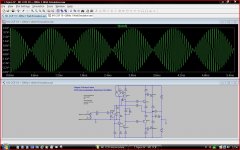
I have always wondered how my lateral FET amp would simulate and whether it would shed any clues as to why it sounds so good sonically, and so, using Bob Cordells excellent book as both a guide and model for teaching me the setups used for running simulations I have been slowing trying to get to grips with LTSpice.
And I know I have a huge amount to learn 🙂
Anyway, for those that don't know it, here is the amp in question,
http://www.diyaudio.com/forums/solid-state/119151-my-mosfet-amplifier-designed-music.html
All the semiconductors including the laterals for the simulation are included in Bobs own models which I downloaded from his website. Which was handy 😉
For anyone interested in running them and having a play around, the LTspice files are all in the zipped folder. For setting up the test procedures I followed Bobs examples.
Attachments
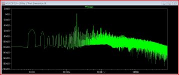
The book has certainly been a huge help to me. I had tried playing with LTSpice briefly a while ago but just couldn't find an easy way into it. I needed the button (key by key) approach as a starting point to get me into it all.
I can certainly see the value of it for looking at trends in the way a circuit functions and so on but I wonder how close to reality the results are.
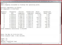
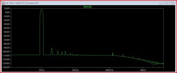
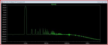
Just for fun, here is the amp with HEXFET's. Distortion of 0.00097% at 70 watts RMS.
Is it really that low ?
I then found by unbalancing the emitter resistors of the drivers, that I can halve that to 0.00043%. The 20Khz figure is relatively unchanged. Look at R1 and C1 (I put a 100uf in series to preserve DC conditions). If you change R1 from 100K down to 750 ohm the distortion at 1Khz appears to drop by 50%.
I have also simmed the full amp (with servo) so that the settling time can be seen and have another one with 5 volts pk pk of triangular ripple on the rails. Thats a bit severe but an interesting one non the less. A little R/C decoupling on the rails to the front end and VAS works wonders at reducing that. Results like that I trust more than the distortion sims at the moment.
I can certainly see the value of it for looking at trends in the way a circuit functions and so on but I wonder how close to reality the results are.
Just for fun, here is the amp with HEXFET's. Distortion of 0.00097% at 70 watts RMS.
Is it really that low ?
I then found by unbalancing the emitter resistors of the drivers, that I can halve that to 0.00043%. The 20Khz figure is relatively unchanged. Look at R1 and C1 (I put a 100uf in series to preserve DC conditions). If you change R1 from 100K down to 750 ohm the distortion at 1Khz appears to drop by 50%.
I have also simmed the full amp (with servo) so that the settling time can be seen and have another one with 5 volts pk pk of triangular ripple on the rails. Thats a bit severe but an interesting one non the less. A little R/C decoupling on the rails to the front end and VAS works wonders at reducing that. Results like that I trust more than the distortion sims at the moment.
Attachments
To anyone following this there will hopefully be more generally related info here,
http://www.diyaudio.com/forums/soft...tings-inconsistent-results-2.html#post2939091
http://www.diyaudio.com/forums/soft...tings-inconsistent-results-2.html#post2939091
- Status
- Not open for further replies.