G'day Guys,
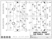
I've been playing around with Mark Johnson's UDP3 in LTspice.
Firstly to understand what its doing and secondly to modify it to my purpose.

I don't understand the 2nd stage clamped capacitance multiplier entirely and I can't find a model for the AZ431AZ so that I can simulate it.
From what I can figure out the purpose of this subcircuit is to set the output voltage at 19v (aside from the reduction in ripple).
I would like to be able to use the UDP3 for input voltages other than the specified 22vac and output voltages other than 19vdc.
With this goal in mind it seems like the clamped capacitance multiplier subcircuit should be modified or dropped to allow the extra flexibilty.
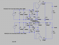
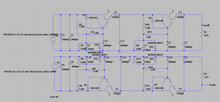
I've whipped up a sim in LTspice however I am very new to simulation so please forgive me if things are not done well.
I have omited everything up to and including the rectifiers as unimportant for the work at hand.
I have also omited the ferrite beads as I can't figure out how to sim them properly. I don't think these are very important for the sim anyway.
I couldn't get a model for the TIP122 to work so I am using the model for the TIP142 as close enough for my purpose.
So starting with the first capmx stage, here's what I have come up with.

For 25vdc in, I am getting 3v drop which seems reasonable.
With a 0.35Vrms input ripple. I am getting 3.4mVrms out.
40db reduction in ripple according to my calculation.

Adding a 2nd stage the same as the first drops another 3v and gives me ripple so low I can't see any in the sim even with the scale set to pV.
So a couple of questions to get the ball rolling.
1)Are my assumptions reasonable so far?
2) Is 350mVrms a reasonable ripple voltage for something like a 150mA load
3) Is there a way to figure out what the ripple is in the sim when it is so low the line is flat on a 1pv scale?
I would like to figure out what improvement in ripple reduction would be from adding a second stage.
My main use case for this circuit will be as a 'pre-regulator' before a VRDN style denoisered LM317/337 in place of a CRC filter.
So the ultimate question is:
If one was to simply chop off the clamped capacitance multiplier and put it in front of a denoiser, is there much benefit to adding a 2nd capmx stage?
I've been playing around with Mark Johnson's UDP3 in LTspice.
Firstly to understand what its doing and secondly to modify it to my purpose.

I don't understand the 2nd stage clamped capacitance multiplier entirely and I can't find a model for the AZ431AZ so that I can simulate it.
From what I can figure out the purpose of this subcircuit is to set the output voltage at 19v (aside from the reduction in ripple).
I would like to be able to use the UDP3 for input voltages other than the specified 22vac and output voltages other than 19vdc.
With this goal in mind it seems like the clamped capacitance multiplier subcircuit should be modified or dropped to allow the extra flexibilty.
I've whipped up a sim in LTspice however I am very new to simulation so please forgive me if things are not done well.
I have omited everything up to and including the rectifiers as unimportant for the work at hand.
I have also omited the ferrite beads as I can't figure out how to sim them properly. I don't think these are very important for the sim anyway.
I couldn't get a model for the TIP122 to work so I am using the model for the TIP142 as close enough for my purpose.
So starting with the first capmx stage, here's what I have come up with.

For 25vdc in, I am getting 3v drop which seems reasonable.
With a 0.35Vrms input ripple. I am getting 3.4mVrms out.
40db reduction in ripple according to my calculation.

Adding a 2nd stage the same as the first drops another 3v and gives me ripple so low I can't see any in the sim even with the scale set to pV.
So a couple of questions to get the ball rolling.
1)Are my assumptions reasonable so far?
2) Is 350mVrms a reasonable ripple voltage for something like a 150mA load
3) Is there a way to figure out what the ripple is in the sim when it is so low the line is flat on a 1pv scale?
I would like to figure out what improvement in ripple reduction would be from adding a second stage.
My main use case for this circuit will be as a 'pre-regulator' before a VRDN style denoisered LM317/337 in place of a CRC filter.
So the ultimate question is:
If one was to simply chop off the clamped capacitance multiplier and put it in front of a denoiser, is there much benefit to adding a 2nd capmx stage?
A denoised LM317/337 is allready dead quiet. Dont forget you will be feeding opamps that have 80dB+ Power supply noise rejection. at a certain point there are diminishing returns to investing more in filtering.
Your assumptions are pretty reasonable to me.
350mV RMS noise on a 2200uF filtered rail is reasonable. check PSUD2
if the line is flat on a 1pV scale it sims well, but keep in mind simulations are rose colloured in comparison to the real world.
If you only expect 150mA load or so, put some resistance in series with the transformer before the bridge, 3R3 or so. so the radiated emissions from the main filter capacitor charge peaks are less.
You may enjoy teaching yourself how to use the LTSPICE feature called ".AC analysis", and then running a half dozen AC-to-DC linear power supply topologies through .AC simulations, just to see how they behave. What are the similarities and differences among the possibilities, etc.
I suspect you'll discover that power supplies with negative feedback have a completely different "shape" of PSRR curve, compared to power supplies without negative feedback. This was hinted in post #1 of the UDP3 thread, quoted below. FYI, the LM317 regulator IC includes negative feedback -- lots of it -- and so do DeNoiseAtor circuits which embed an LM317. They will give you NFB shaped PSRR curves.
One nice feature of .AC analysis is that, unlike .TRANsient analysis, .AC easily and accurately deals with circuits and signals having enormous dynamic range. .AC analysis can tell you when a cascade of filters has a PSRR of -200 dB: a reduction of ten billion fold (1E-10). SPICE transient analysis doesn't have nearly enough dynamic range to accurately simulate and report such results. Your results in post #1 of this thread suggest that your .TRANsient studies are unable to simulate PSRR below about -70 or -80dB.
It's a good use of ten minutes of your time, to work backwards from the Pearl3 supply rails all the way back to the bridge rectifier output pins. Start with the maximum ripple you are willing to tolerate on the Pearl3 supply rails, and end with the ripple you get at the bridge rectifier output. Divide those two numbers, take the base 10 logarithm, and multiply by twenty to get dB. Voila! You now have your own PSRR design goal. Just make sure you hit the PSRR goal at all frequencies between, say, 10 Hertz and 50 kiloHertz. There is crud and noise and schmootz on the AC mains at all frequencies, which the rectifiers conduct into your DC power supply circuits. You need to prevent this undesirable ick-stuff from flowing down the Umbilical Cable and into the Pearl3.
I suspect you'll discover that power supplies with negative feedback have a completely different "shape" of PSRR curve, compared to power supplies without negative feedback. This was hinted in post #1 of the UDP3 thread, quoted below. FYI, the LM317 regulator IC includes negative feedback -- lots of it -- and so do DeNoiseAtor circuits which embed an LM317. They will give you NFB shaped PSRR curves.
The UDP3 circuit is a cascade of several lowpass filters connected in series; it is NOT a voltage regulator and there are no negative feedback loops. This is intentional and deliberate; NFB loop gain generally falls as frequency rises, often at a slope of -20dB per decade of frequency. But we want lots of attenuation (a/k/a "PSRR") at high frequencies, exactly where NFB regulators poop out.
One nice feature of .AC analysis is that, unlike .TRANsient analysis, .AC easily and accurately deals with circuits and signals having enormous dynamic range. .AC analysis can tell you when a cascade of filters has a PSRR of -200 dB: a reduction of ten billion fold (1E-10). SPICE transient analysis doesn't have nearly enough dynamic range to accurately simulate and report such results. Your results in post #1 of this thread suggest that your .TRANsient studies are unable to simulate PSRR below about -70 or -80dB.
It's a good use of ten minutes of your time, to work backwards from the Pearl3 supply rails all the way back to the bridge rectifier output pins. Start with the maximum ripple you are willing to tolerate on the Pearl3 supply rails, and end with the ripple you get at the bridge rectifier output. Divide those two numbers, take the base 10 logarithm, and multiply by twenty to get dB. Voila! You now have your own PSRR design goal. Just make sure you hit the PSRR goal at all frequencies between, say, 10 Hertz and 50 kiloHertz. There is crud and noise and schmootz on the AC mains at all frequencies, which the rectifiers conduct into your DC power supply circuits. You need to prevent this undesirable ick-stuff from flowing down the Umbilical Cable and into the Pearl3.
Last edited: