P PeteMcK Member Joined 2002 2009-08-25 2:12 am #1 2009-08-25 2:12 am #1 I once built a simple compressor from Elektor, lost the schematic aeons ago. It looked something like the attached pic. Would it work as drawn, and if so, any suggestions for component values? Attachments comp.JPG 6 KB · Views: 794 M musimedia Member Joined 2009 musimeda.ca 2012-04-19 5:31 pm #2 2012-04-19 5:31 pm #2 Hi, i know this is an old thread, but did you get this working ? Thanks, Mike. A AndrewT R.I.P. Joined 2004 2012-04-19 6:07 pm #3 2012-04-19 6:07 pm #3 I think for -ve DC it works, the diode is inverted. As the cap voltage increases the FET turns off, increasing the attenuation. But what happens with +DC and more importantly with an AC signal? Status Not open for further replies. Share: Facebook X (Twitter) LinkedIn Reddit Pinterest Tumblr WhatsApp Email Link
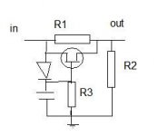
I once built a simple compressor from Elektor, lost the schematic aeons ago. It looked something like the attached pic. Would it work as drawn, and if so, any suggestions for component values?
M musimedia Member Joined 2009 musimeda.ca 2012-04-19 5:31 pm #2 2012-04-19 5:31 pm #2 Hi, i know this is an old thread, but did you get this working ? Thanks, Mike. A AndrewT R.I.P. Joined 2004 2012-04-19 6:07 pm #3 2012-04-19 6:07 pm #3 I think for -ve DC it works, the diode is inverted. As the cap voltage increases the FET turns off, increasing the attenuation. But what happens with +DC and more importantly with an AC signal? Status Not open for further replies.
A AndrewT R.I.P. Joined 2004 2012-04-19 6:07 pm #3 2012-04-19 6:07 pm #3 I think for -ve DC it works, the diode is inverted. As the cap voltage increases the FET turns off, increasing the attenuation. But what happens with +DC and more importantly with an AC signal?
I think for -ve DC it works, the diode is inverted. As the cap voltage increases the FET turns off, increasing the attenuation. But what happens with +DC and more importantly with an AC signal?