So over the last two days I put together the three circuits shown below. I really want to start getting a better understanding of the basics of solid state power amps. I built them one at a time, and when each one was finished I listened to it for about an hour, really trying to listen to the sound of it. I was hoping to ask a couple of questions. Here is what I came up with:
Little Amp1 - It sounded good. Nice lows and highs, maybe just a slight hint of distortion. Sounded like the middle was very slightly scooped out. It kind of sounded like all of the consumer amps I have owned over the years, low priced, integrated amps. Nothing special, just decent.
Question - I'm not sure what class this amp is biased at. ( first novice question 😱 ).
Little Amp 2 - A little more distortion, completely different sound. Less low end but more pronounced from the upper low end to the high end. More grainy. Not smooth from top to bottom like amp1. ( this is the first time I've tried to explain the sound of something ). It kind of started to grow on me the more I listened.
Little Amp 3 - More distortion. Had a hard time biasing the 1/2 Vcc. Just took a while to finally settle down. After that it never really did sound right. It did sound more like amp 2 than amp 1 though.
I used fairly good parts for these amps. The transistors were what was spec'ed on the schematic. The resistors were 1% metal film 1/2 and 1 watt. Caps were all newer. The power supply was an adjustable, regulated supply.
I know I could just build a JLH, or a Pass amp as a good starting amp, in fact I just finished a little solid state, p to p stereo amp for my daughter, but it was well documented and easy to build. I want to understand a little better what happens and how the sound improves when I add, (or subtract) parts to a circuit.
So starting with Little Amp 1, I would like a couple of suggestions on adding two or three parts, one at a time, so I can listen to the difference, (improvement) it makes. I did order Bob Cordell's book but I'm itching to get started now. Thanks.
Tom
Attachments
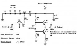
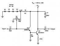
Little amp #1: Assuming 8 ohm load, you get 25 mW (order of magnitude) in class A, from the 46mA quiescent current shown on the schematic (~80mA peak output). After that it would be pretty nasty I think. I expect high distortion even in the class A range.
It's basically the JLH simple class A output stage without global negative feedback. Because of that, you've needed to remove the bootstrap from R4 to set the gain. Increasing the current is my first suggestion.
After that, maybe restore the R4 bootstrap and apply global negative feedback.
It's basically the JLH simple class A output stage without global negative feedback. Because of that, you've needed to remove the bootstrap from R4 to set the gain. Increasing the current is my first suggestion.
After that, maybe restore the R4 bootstrap and apply global negative feedback.
Little Amp 1:So starting with Little Amp 1, I would like a couple of suggestions on adding two or three parts, one at a time....
- Replacing R4 with a potentiometer would be a good start, so you can adjust the quiescent current (preferably higher).
- The next step would be to try bootstrapping it as in the first pic below. Making C4 a lot bigger than 220uF is probably a good idea. R5 could probably be bigger too.
Little Amp2:
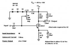
- Reducing R3 from 50R to say 10R and increasing the quiescent current would allow higher output and probably lower distortion at the same output level. It will also improve the loudspeaker damping, which may sound better or worse.
- Removing C4 will result in less gain, but also much lower distortion.
- Putting an emitter follower in front of Q1, as in the second pic below, will make the amp much easier to drive.
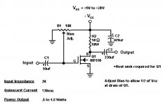
Little Amp3:
- As with Little Amp 1, try reducing R2 and increasing the quiescent current.
- Putting a small resistor in series with the MOSFET source will improve linearity.
Attachments
Little amp #1: maybe restore the R4 bootstrap and apply global negative feedback.
Little Amp 1:
- Replacing R4 with a potentiometer would be a good start, so you can adjust the quiescent current (preferably higher).
- The next step would be to try bootstrapping it as in the first pic below. Making C4 a lot bigger than 220uF is probably a good idea. R5 could probably be bigger too.
Improved #1 circuit - Simple Amplifier 😉
As far as Little Amp 1, I added the bootstrap and built the amp as per Godfrey's suggestion. Result:
1. It was really hard to drive. I'm using my laptop output and I couldn't get it loud enough. How can I make it easier to drive?
2. Now that I have the bias pot and the bootstrap pot, I'm not sure how to adjust them. I'm assuming the bias pot still adjusts the quiescent current at the collector of Q3.
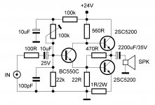
I also built Lazy Cat's amp. It started out really distorted, (overdriven) so I changed out BC550 for a 2N3904. That really seemed to help a lot. Should mention that I'm using 2N3055's for output transistors. Also, how could I add a high pass filter to it? Am I still adjusting half of Vcc at collector of Q3? Thanks.
Tom
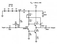
Pot 1 adjusts the DC voltage at the junction between Q2 and Q3. That should be set to about half the supply voltage. It will work better if you take out the 22K resistor and connect the left side of the pot to ground, like in the pic below.As far as Little Amp 1, I added the bootstrap and built the amp as per Godfrey's suggestion. Result:
1. It was really hard to drive. I'm using my laptop output and I couldn't get it loud enough. How can I make it easier to drive?
2. Now that I have the bias pot and the bootstrap pot, I'm not sure how to adjust them. I'm assuming the bias pot still adjusts the quiescent current at the collector of Q3.
Pot 2 adjusts the quiescent current of Q2 and Q3. You can check that by measuring the voltage across R6.
Attachments
I'll try that tonight. Novice question #2, what voltage am I looking for across R6? Will this determine whether this amp is biased class A, AB or B? Also wanted to say thanks for your help and expertise. To Lazy Cat and steveh49, thanks too.
Tom
Tom
Last edited:
Pot 1 adjusts the DC voltage at the junction between Q2 and Q3... Pot 2 adjusts the quiescent current of Q2 and Q3. You can check that by measuring the voltage across R6.
Other way around. Pot 1 sets the currents and Pot 2 sets the output voltage (for a given value of P1).
Tom, this amplifier has to be biased in class A. It will be awful once you go outside that. Idle current of Q2 & Q3 = voltage across R6 divided by R6 (Ohm's law V=IR). Work out how much output power you want and then set the idle current to about 2/3 the max output current. Depending on how much power you want, you might need to adjust the Q1 current as well by changing R5.
Have you drawn the schematic in a simulator? Running the sim would teach you a lot.
Are you using headphones? The output capacitor seems sized for a higher impedance load than typical speakers.
Yes, my bad. 😱Other way around. Pot 1 sets the currents and Pot 2 sets the output voltage (for a given value of P1).
I also built Lazy Cat's amp. It started out really distorted, (overdriven) so I changed out BC550 for a 2N3904. That really seemed to help a lot.
Hi Tom
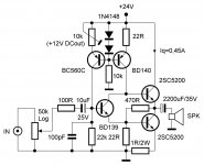
Voltage gain is 27dB (*22,36) that is obviously too sensitive for your source level, so I added input potentiometer. The main problem of such simple circuits is that drive stages simply run out of current to sufficiently supply the output bases, especially if the outputs are low hFE like 2N3055. Resistors from previous sch are now replaced with CCS (constant current sources) which will do the job, although circuit is not so simple anymore, but will work much better. 😉
Hi TekkoLC, wat proggy do u draw ur schemos in ?
P-CAD with my own symbol library according to my taste. 😉
Attachments
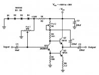
Thinking about Little amp 1, I realised that with the bootstrap, if you want the output signal current to be shared equally between Q2 and Q3, then the resistor between Q1's emitter and ground should be removed.
Playing in the simulator, I had reasonable results with the circuit below, but noticed that with C2 = C3 = 220uF, there is a peak in the bass response, even with a purely resistive load. Increasing the output cap to 1000uF tames that, but I'm sure the response will still be all over the place with a real speaker.
Playing in the simulator, I had reasonable results with the circuit below, but noticed that with C2 = C3 = 220uF, there is a peak in the bass response, even with a purely resistive load. Increasing the output cap to 1000uF tames that, but I'm sure the response will still be all over the place with a real speaker.
Attachments
Godfrey, it looks as though your circuit has a very high impedance output (i.e. current source). Was that intended?
"with C2 = C3 = 220uF, there is a peak in the bass response"
That surprised me given that I though the output capacitor was undersized. I get the same result, apparently caused by the Q2 input impedance increasing at low frequencies as its emitter is unloaded by the undersize cap.
"with C2 = C3 = 220uF, there is a peak in the bass response"
That surprised me given that I though the output capacitor was undersized. I get the same result, apparently caused by the Q2 input impedance increasing at low frequencies as its emitter is unloaded by the undersize cap.
Last edited:
you have three caps in there each defining their own roll off characteristic. Then there are some parasitic caps, but hopefully they only affect the higher frequency performance.
Try simulating with all 3 caps increased ten-fold. Then reduce one at a time to see where the cap impinges on the low bass performance.
Try simulating with all 3 caps increased ten-fold. Then reduce one at a time to see where the cap impinges on the low bass performance.
I've been listening to Godfrey's last circuit post for about an hour now. It really sounds pretty good to me. I am running a quiescent current of ~.700A and a 1/2 Vcc of ~12V. I have the output transistors mounted on a good size heatsink. I have changed the output transistors to Toshiba 2SD845's, (not for any reason other than I had them). Below is the circuit I'm running with actual values. I'm wondering if the longer I run it and listen to it, it seems to be getting slightly more distorted. Just not sure if it was there from the beginning or not. I drew my schematic in LTspice because I think it's easy to make schematics in, but I'm still not great at simulating with it yet. I will probably change Q2 and Q3 to 2N3055, (in spice and on the breadboard), so I can simulate.
Tom
(I forgot the ground symbol on the schematic)
Tom
(I forgot the ground symbol on the schematic)
Attachments

Thinking about Little amp 1, I realised that with the bootstrap, if you want the output signal current to be shared equally between Q2 and Q3, then the resistor between Q1's emitter and ground should be removed.
Playing in the simulator, I had reasonable results with the circuit below, but noticed that with C2 = C3 = 220uF, there is a peak in the bass response, even with a purely resistive load. Increasing the output cap to 1000uF tames that, but I'm sure the response will still be all over the place with a real speaker.
The bootstrap resistors ratio is not adequate as most of the voltage
is lost around the pot so there will be few effective bootstrap.
Increase the 100R resistor to about half the necessary value ,
that is about 270R and give the pot a value of 500R , this will
allow about 6mA current once the voltage is at half the PS value.
Also , a 4.7K resistor in serial with the input transistor
base will rectify the eventual high frequency peaking
that will inevitably occur with a low Z source.
Other than that , distorsion will be inherently high.
I'm wondering if the longer I run it and listen to it, it seems to be getting slightly more distorted.
Forget about the bootstraps, your circuit desperately needs CCS & feedback. 😉
Yes, over most of the audio band, the output impedance is high. However at low frequencies the bootstrapping is less effective and the output impedance falls. This means that, ignoring the output capacitor, the output impedance is inductive at low frequencies. I think it's the interaction between that and the output capacitor that can cause a peak in the response before it rolls off.Godfrey, it looks as though your circuit has a very high impedance output (i.e. current source). Was that intended?
"with C2 = C3 = 220uF, there is a peak in the bass response"
That surprised me given that I though the output capacitor was undersized. I get the same result, apparently caused by the Q2 input impedance increasing at low frequencies as its emitter is unloaded by the undersize cap.
The bias is probably changing as it heats up. You might want to re-adjust the potentiometers to give the correct bias when the amp is fully warmed up.I'm wondering if the longer I run it and listen to it, it seems to be getting slightly more distorted....
Bad Kitty!Forget about the bootstraps, your circuit desperately needs CCS & feedback. 😉
What's the matter, don't you like 2'nd harmonic distortion and high output impedance?
😀
Bad Kitty!
What's the matter, don't you like 2'nd harmonic distortion and high output impedance?
😀
You know as I know that for the input BJT's base and collector we need to supply constant current if we want a static/dynamic operating conditions to be within linear area, anything less than that is just patching. 😉
- Status
- Not open for further replies.
- Home
- Amplifiers
- Solid State
- Simple amp circuit obsevations