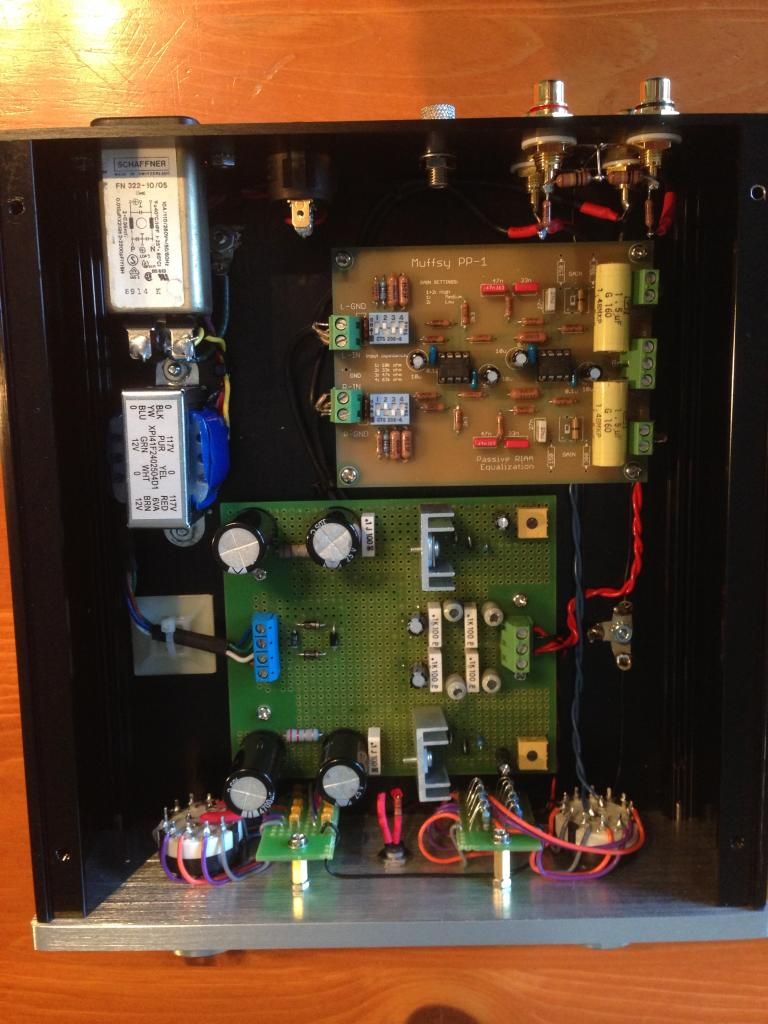
Finished a phono preamp build. Used a cheap EI transformer to generate the AC voltage needed for the +12V/-12V. When I powered the preamp up I got hum. After some troubleshooting I decided to power the preamp with two 9V batteries, bingo no hum!
Next thing I do is energize the transformer but leave the secondaries disconnected. Testing for hum that is being coupled to the audio signal. Doing this I got hum again.
I added an IEC filter as I suspected there was some DC on the incoming AC power line. This helped a great deal with the hum but some still persists.
What can I do to minimize the hum now? I have lots of copper shielding tape left over from shielding a guitar. I don't really want to go buy a toroidal transformer.
Here is a pic for reference (click to enlarge)
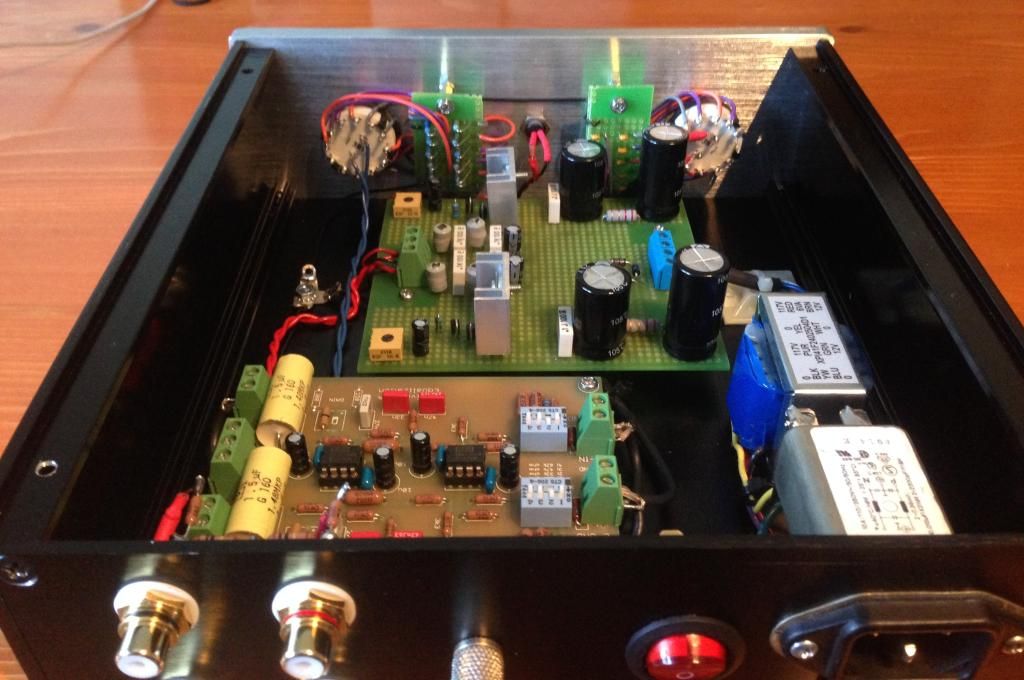


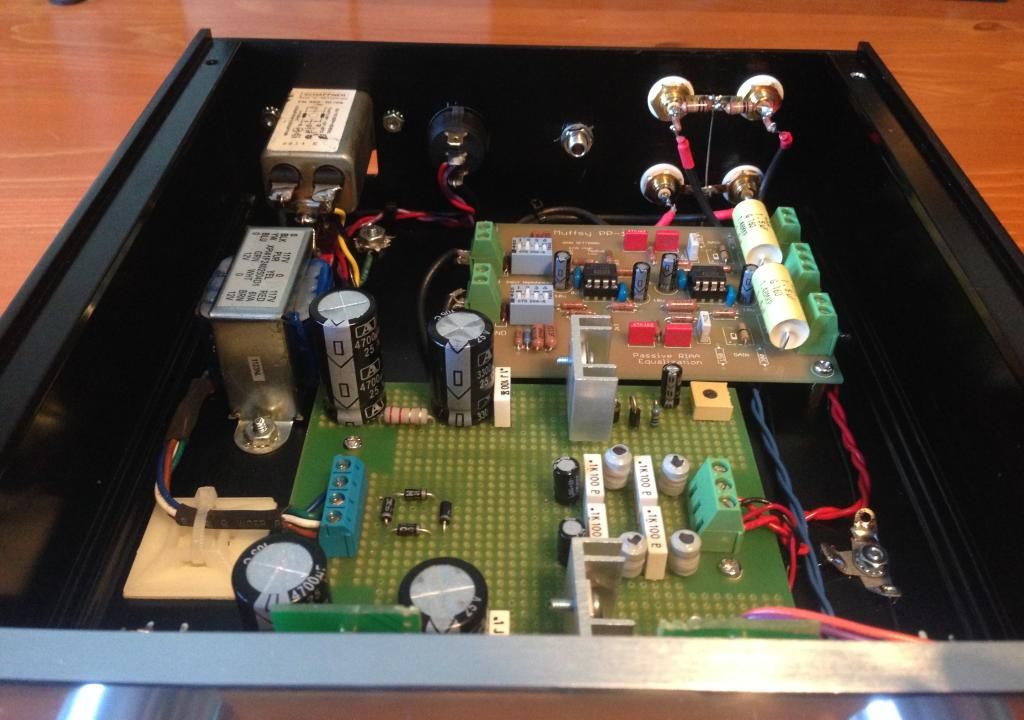
What can I do to minimize the hum now? I have lots of copper shielding tape left over from shielding a guitar.
I don't really want to go buy a toroidal transformer.
Try rotating the transformer 90 degrees, moving it closer to the supply board, adding a steel partition between
the 120VAC part and the phono, or mount it outside the chassis on the back panel. Or, use a couple of DC wall warts
instead of the transformer. With the wall warts, you could keep the supply pcb as is, even the rectifier diodes could stay.
Last edited:

Would a steal partition just be a piece of steel between the transformer and the PCBs?Try rotating the transformer 90 degrees, moving it closer to the supply board, a steel partition,
or else mounting it outside the chassis on the back panel.
Would a steal partition just be a piece of steel between the transformer and the PCBs?
Yes, bolted to the chassis.
I can buy some 20 gauge (1mm) galvanized sheet metal steel locally. I could then use some L brackets and mount it as such. Is this what I want?

I can buy some 20 gauge (1mm) galvanized sheet metal steel locally. I could then use some L brackets and mount it as such.
Sure, you could even bend the bottom edge and bolt it directly to the chassis.
That would probably work better. Maybe even bend the top edge over the transformer as well.
You can probably get away without any shielding, just by rearranging the elements in a more sensible way.
For example, if the dimensions allow, attach the preamp board to the lateral panel opposite to the transformer.
For example, if the dimensions allow, attach the preamp board to the lateral panel opposite to the transformer.
yes, i will re-orient the line amp board so that the higher impedance input is farthest from the traffo....
yes, with Japanese equipment, this is common practice...
I thought this was interesting: How to reduce Hum
yes, with Japanese equipment, this is common practice...
Thanks for all the suggestions.
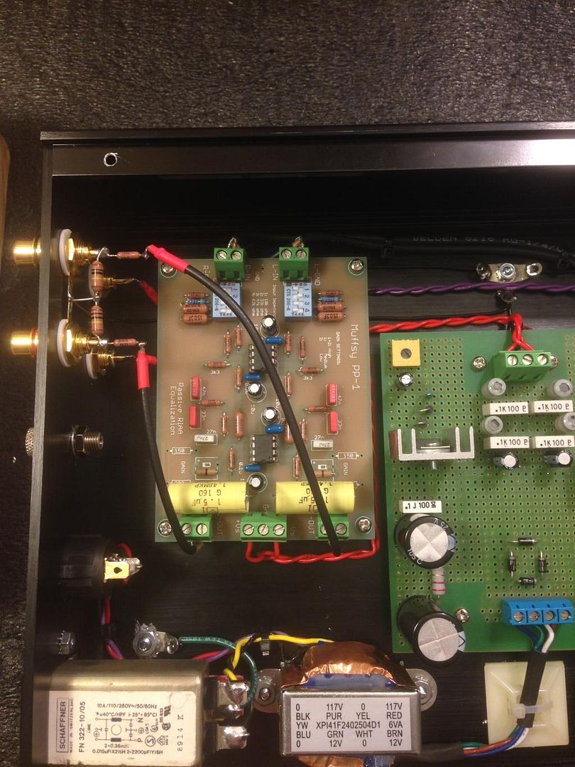
In my attempts to keep things neat and looking nice I see the errors of my ways. While initially laying things about I did think about moving the high impedance input side to where the low impedance outputs are but decided not to in order to keep the +12V/-12V run short and looking neat. I didn’t think the transformer coupling would happen...oh well, I’ve learned something new.
I am going to try shielding first. Based on that I will reorient the preamp (line) board if need be.
I found useful to wrap a copper band around the transformer, so that it forms a shorted turn, but outside of the iron core. It will effectively shunt stray magnetic field. Solder the ends together.
Be careful about taking advice from someone who appears to be confused himself. A flux/belly band does not have to be tight, but it does need to be very low resistance. It acts as an external shorted turn. In any other configuration copper will be useless as a magnetic shield, as he found.Fusor said:I thought this was interesting: How to reduce Hum
For shielding you need soft iron; stainless steel is the opposite of this! As would be expected, he found this didn't work.
His final solution is a simple piece of steel, bent into a shape which by experiment seems to reduce the coupling. I guess what this is doing is modifying the field by providing an alternate path for some of the 'flux lines'.
DC supply rails don't have to be short or neat. Signal wires may need to be short, but don't have to be neat. AC power wiring needs to be kept well away from signals.ChrisM91 said:While initially laying things about I did think about moving the high impedance input side to where the low impedance outputs are but decided not to in order to keep the +12V/-12V run short and looking neat.
Why do you say that?Read Daniel Joffe's paper on ground loops.
I suspect your solution lies in that article.
I have a safety ground for my IEC jack. And I have a ground point for all other grounds. The only exception is the turntable ground terminal that is not isolated from the chassis (thought I don't think that is an issue).
I was aware well filtered DC would not be an issue but chose the layout for what I thought would make wiring simplier. In retrospect the low impedance output wires should have been the ones closest to the AC wires.DF96 said:DC supply rails don't have to be short or neat. Signal wires may need to be short, but don't have to be neat. AC power wiring needs to be kept well away from signals.
Are you suggesting I take a peice of copper tape and wrap it around the plastic wrapped ends of the bobbin, making sure the copper has continuity all the way around? This is essentially a flux band on a transformer that does not have one. No?lcasazar said:I found useful to wrap a copper band around the transformer, so that it forms a shorted turn, but outside of the iron core. It will effectively shunt stray magnetic field. Solder the ends together.
Last edited:
"Are you suggesting I take a peice of copper tape and wrap it around the plastic wrapped ends of the bobbin, making sure the copper has continuity all the way around? This is essentially a flux band on a transformer that does not have one. No?"
Yes but the copper tape should wrap around also the iron from outside, not only the bobin.
Yes but the copper tape should wrap around also the iron from outside, not only the bobin.
I thought this was interesting: How to reduce Hum
That is very interesting.
Love it when people just try things.
Almost as much as when people post such things and bring them to our attention.
Thanks,
I think the layout of components in a confined space will continue to produce more or less of hum regardless of shielding you provide to transformer. Stray fields will continue to leak until the transformer is completely sealed in shielding enclosure which is thick enough. In such a sensitive piece of equipment as phono preamp, power transformer, rectifier and smoothing capacitors are best left out of the main box and put in a separate one. Unstabilized voltages are then passed into main box. In fact, many manufacturers, such as Benz Micro PP1 follow that path in their shoebox-size designs.
Last edited:
the diy flux/belly band has some risk of violating the safety rating of the xfmr if not properly insulated and with attention to required creepage and clearance
the large spacing of PS components on the perfboard makes me suspect ground hierarchy, loop minimization may also need attention
the large spacing of PS components on the perfboard makes me suspect ground hierarchy, loop minimization may also need attention
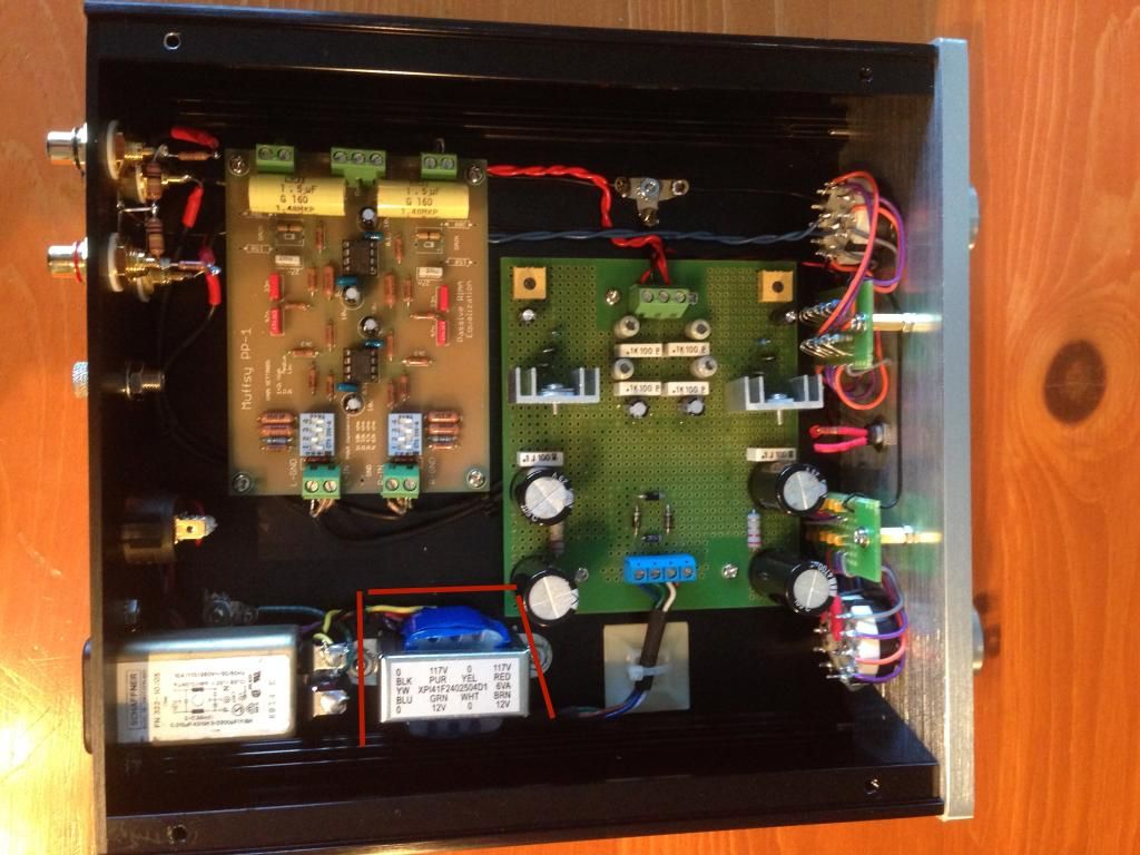
I moved around the input and output. To my ears this reduced the hum.
Next I shielded the transformer with copper tap. Is this what you meant lcsaszar, or do I need to do more?
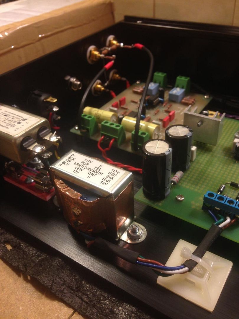

Next I shielded the transformer with copper tap. Is this what you meant lcsaszar, or do I need to do more?

Read Daniel Joffe's paper on ground loops.
I suspect your solution lies in that article.
Why do you say that?..........................
Further evidence that you have aerial Loops that are transmitting and/or emitting interference.I moved around the input and output. To my ears this reduced the hum.....................
- Home
- Source & Line
- Analogue Source
- Shielding EI Transformer