I'm planning to modify an old Sherwood S7300 with new power amp and preamp sections. I've done this before.
The power amp will be a clone of ostripper's Wolverine with near-PPM THD and short circuit protection. It'll use an SSLR for DC speaker protection and muting.
There are no coupling caps in the power amp. This power amp will be permanently mated to its preamp; a coupling cap at the preamp input will maintain zero DC offset throughout. There are no electrolytics in the signal path and only 3 caps total in the signal path. All are small enough that you could use film types. I'll probably use c0g ceramics, they're small and cheap and measure near zero distortion.
The preamp is a single gain stage with non-inverting Baxandall tone controls. I'm planning to use a spare pair of OPA627s.
This Baxandall network isn't symmetrical, it has a gain of 3. That introduces a quirk: to set the tone controls to flat, the original pots should be turned to a 25K/75K position at about 3:00 o'clock or so. You could fix that by adding extra resistance in the tone network, though that would raise the noise floor. I'll probably just mark a new center position in pencil on the front panel.
There are some nice original features of this Sherwood that I'll preserve:
* It has good grounding discipline, there's a dedicated signal ground parallel to the signal path which carries no unnecessary current.
* The volume pot is only 50K, not 100K as in a lot of 70s gear, so that's less noisy.
* The physical layout of the power supply will allow the half-wave output currents to be kept far from small signals. (Well; the power supply is a little bit close to the tone board, it could use a piece of shielding. It's not horrifying.) There's room to build the whole output stage on the rear of the heatsinks, opposite the amp input and driver stages, for better isolation of those half-wave currents.
* Let us praise 39V rails; they make SOAR protection pretty easy even with a single output pair. Simulating with a 4R load, the modified amp can drive the output to over 30V peaks before distortion exceeds -100db as current limiting is just starting to kick in. That's over 110 wpc, if I did the math right. The power supply probably couldn't keep up with a 110wpc test tone, but you'd have a chance to hit musical peaks in that vicinity.
Schematics to follow.
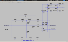
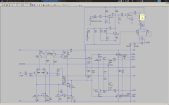
schematics
Here's the LTSpice deck; the two files ending in '.asy.txt' should be renamed to '.asy' instead so that spice can recognize them.
Plus, png's for the amp and preamp.
There are some inaccuracies here:
* The real amp will likely use 2SA1507 and complement for drivers, I just don't have spice models for those.
* "R41" in the protection circuit is not really a gigohm resistor, it's really a wire. That just fools spice into unmuting the muting circuit from the outset of simulation.
* The PC817D optoisolator and its associated voltage source and 680R, those aren't real. The real circuit will use a PVI5013R in this place, like this one.
Attachments

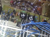
It took a year, and this crazy dream is now a reality. It's a REAL stereo! The kind with TWO working channels. It sounds great.
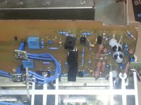
1st pic shows the overall layout. Modern ONsemi outputs are mounted on those little PCBs on the original heatsinks. The output transistor mounts include the emitter resistors and zobels, the idea is to keep all the big half-wave currents on the far side of the heatsinks, far from the small signal stages.
2nd pic is the amplifier frontend. This is both channels' frontends on one PCB.
3rd pic is the driver stage, including protection SSLR.
Ignore last year's schematics, it's evolved a lot.
Bringup was easy. I used a variac and a dim-bulb. Weeks earlier, I brought up the amp PCBs without an output stage (jumpering direct from one of the driver's emitters to the NFB line to close the loop.) That configuration permitted doing some early troubleshooting with stiff resistors, like hundreds of ohms, in series with the rails for safety.
I put everything on connectors to facilitate easy debug and rework. My main regret is not researching different types of connectors to pick the best fit. I used familiar 100-mil-spaced SIP jumpers and headers and made little PCBs to form each connector. In hindsight, this was time consuming and these little headers seem too flimsy for their critical task.
Better would have been .156"-spaced friction lock connectors. My Sherwood HP-1000 came from the factory with these and they seemed plenty robust and unlikely to ever come loose.
Attachments

Last edited:
- Status
- Not open for further replies.