---- Story
This is a unit purchased from Scotland more than 20 years ago. It has been used only for some months (1997?), since then it is out of order, with several issues and packed, some transistors changed back then, but because of a lost board bridge and maybe some other parallel problems, it has been abandoned and stored, one blink before recycle but decided to store...
This was a nice sounding machine with lots of power, (worth to be fixed? for me, yes)
This is more or less a personal test, to see some very basic stuff about amplifiers and their electronics, just for fun, and why not, be able to fix it by guidance. No need for pro repair right now. So with very basic knowledge, one simple soldering gun and a very basic multimeter...
----- Current state:
So, this is what I already have done until now. Some discoveries, some brutal fixes. I will not connect it to my speakers until some measurements will turn to normal. I will have to find a spear cheap woofer though to test (only headphones for now). So the story continues to present time like this:
1.Relay issue.
Power up, no screen, no sound, only 2 LEDs on, a very short strange relay click (!), so to check the power supply board. I have found the relay to be out of order. So I opened it and shorted with a wire. => Screen is now open! Still no sound (I repeat only headphones tested), every button function responds, remote responds to all commands also! Relay needs exact replacement (30V DC).
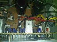
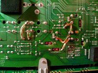
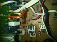
2. Broken main board soldering on multiple points:
(see picture with brutal but maybe good fix)
A rectifier ic totally unstuck from the board, no way to fix it with my tools, but I have thought of bypassing with some wires. It seems to work ok and the bond is tough also. It is the IC109, with probably good measurements IN: 21V (or 25V) OUT: 15V but I am not sure as I have not noted it. near rectifier: IN 23V OUT 6V etc... 21V (or 25V) to 15V... seems good.
Same issue with the 2nd transformer output to main board (both measure @ 44V AC), broken. So bypassed with wires to the rectifier diodes. Bond seems/feels ok too. Now all diodes have power of 30V and near capacitors (the big 15000uf) 60V (and can hold 60V after switching off).
Facts: Now the amp board seems to have power. Now some of the transistors seem to produce heat, only the L channel IC PNP Q214L feels frozen, R and C (only UPfront)... trasistors measured to 60V and L channel 0V. IC PNP Q214R and IC PNP Q214C produce heat on their sinks.
So can the front L channel be the problem? what part can possibly do this?
Is there a correct way to measure transistors without de-soldering them? Do you think that the voltage leak on L-out can be caused from a failed transistor IC?
3. DC offset.
A brutal measurement, one wire to ground, one to the output.
R: below 10mV and dropping
C: start at 50mV and dropping to below 10mV after some seconds
SurR,SurL bellow 20mV and dropping to below 10mV after some seconds
!!!!
front-L --> 60V
Same behavior after switching A and B front speaker output selector when the one is 0V the other is 60V. Even on strand by there is 1V measurement there (with the shorted relay, so there is power from the transformer).
A,B off both 0V
Can this be caused by the main pair of transistors or any close component of the L-channel amplifier?
Is there a possiblility to remove center channel transistors and relpace the faulty L-channel? They are the same type according to schematic, and probably the all three L R C amplifier stages are exactly similar.
ONE IMPORTANT NOTE:
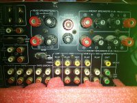
The unit has pre-in and out for all 6 channels, 3x channels (L-R-C) based on 2SA1215 / 2SC2921 and 3x (SurL-SurR-SUB) based on 2SA1360 / 2SC3423 and some 2SC4137. You can find their places and codes on the service manual, something like this. L R C similar amp stages, SurL-R different.
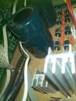
There are "shorting" RCA connectors. 2x SurL-R connectors are missing. See picture.
The unit will be used only in stereo, so no need for fancy surround stuff, but there could be a chance to use surround LR amplifiers using a pre-out connection to the main LR pre-outs so a new pair of front stereo can be used in parallel. (So to use all 4 amplifiers at the same time at stereo mode to gain some loudness e.g. for outdoor use)
But for now maybe I could bypass L-channel amp and use a new RCA connection to pass the L-channel pre-amp signal to center-in amp, and never use L-channel output. Would this be OK?
The 60V signal has to be bypassed somehow, (removing/desoldering L-channel transistors?) so no mistakes will be left for anyone else.
There has been also a strange issue when testing with headphones, no sound just clicks after switching sources, for now I have not a spare speaker to test and I will not connect any good speaker until normal measurements. I will find though a cheap or used woofer to test soon.
4. Headphone/A-B switch board produced heat, and obvious smell/smoke produced, maybe some kind of flux melted I guess, it is working and measured resistances are ok but 2-3 points have been heated up much and maybe fail in near future, see the picture..., this could be caused by the previous described phenomenon (?) I do not know. EDIT: Testing with headphone speakers, L channel has been destroyed by this situation.
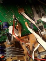
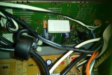
5. Missing ? (cables/connections?).
This connection has Not fixed yet, this can be a protection circuit never connected or simply disordered and lost, maybe optional maybe very important, I do not know. It is supposed to Connect the 2 amp boards. See the picture with the unplugged connector CP203 on amp202 board, there is a free place to solder at amp302. I guess I have nothing to loose. The strange thing is that an other pre-out board cable was connected there by mistake (!!!), witch right position is ssome centimeters on the right of the board.
Also CP411/CN411 connectors cable is hanging around, a missing connector, I do not know what this is about, but heatsink fan is always ON, maybe is the heat sensor? I will connect a custom cable/connector there also.
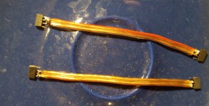
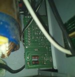
6. Missing board CNT-2 BD
I do not know the use of it, but I have managed to build a brutal wire connector for this, see pictures.
Last issue found,
7. tuner cannot lock to any station even on a good antenna.
Probably same problem as... YouTube
keep in mind I am not an expert, and at first place, I am sorry, if I have already wrote anything misleading because of my ignorance or any mistake passed in this post. Hopefully I have been descriptive enough for experts and clear for novices like me, so we can have a good conversation, there are multiple issues as you can see.. (but many chances for a repair?__ ).
).
thanks... any guidance appreciated...
Service manual link: Dropbox - R725RDS.pdf
Edit 1: Headphones output have destroyed the L headphones speaker while testing, the smoke/melted flux on the relative board has been noted. Headphones has been tested on an other device to find out that the L-speaker has distortion and significant loss of volume.
Edit 2: front L pre out measured at 31-32V at any souce at any level or balance even if no inout signal. All others at mV range same with inpun signal or without. 245mV when power is off.
Edit 3: front L pre out measured at 31-32V, front L main power transistors removed, pre-out remains to 30-32V range and main powered out to 0V. So there might be a chance of the voltage leak to happen before power transistors, maybe in the pre-out stage driver transistor or the close components. But I will not be sure until L channel parts removal and correct measurements and I am not sure if I will continue further for now.
So the repair procedure will froze here, until I will have access to better testing equipment and/or help from a more experienced person.
This is a unit purchased from Scotland more than 20 years ago. It has been used only for some months (1997?), since then it is out of order, with several issues and packed, some transistors changed back then, but because of a lost board bridge and maybe some other parallel problems, it has been abandoned and stored, one blink before recycle but decided to store...
This was a nice sounding machine with lots of power, (worth to be fixed? for me, yes)
This is more or less a personal test, to see some very basic stuff about amplifiers and their electronics, just for fun, and why not, be able to fix it by guidance. No need for pro repair right now. So with very basic knowledge, one simple soldering gun and a very basic multimeter...
----- Current state:
So, this is what I already have done until now. Some discoveries, some brutal fixes. I will not connect it to my speakers until some measurements will turn to normal. I will have to find a spear cheap woofer though to test (only headphones for now). So the story continues to present time like this:
1.Relay issue.
Power up, no screen, no sound, only 2 LEDs on, a very short strange relay click (!), so to check the power supply board. I have found the relay to be out of order. So I opened it and shorted with a wire. => Screen is now open! Still no sound (I repeat only headphones tested), every button function responds, remote responds to all commands also! Relay needs exact replacement (30V DC).
2. Broken main board soldering on multiple points:
(see picture with brutal but maybe good fix)
A rectifier ic totally unstuck from the board, no way to fix it with my tools, but I have thought of bypassing with some wires. It seems to work ok and the bond is tough also. It is the IC109, with probably good measurements IN: 21V (or 25V) OUT: 15V but I am not sure as I have not noted it. near rectifier: IN 23V OUT 6V etc... 21V (or 25V) to 15V... seems good.
Same issue with the 2nd transformer output to main board (both measure @ 44V AC), broken. So bypassed with wires to the rectifier diodes. Bond seems/feels ok too. Now all diodes have power of 30V and near capacitors (the big 15000uf) 60V (and can hold 60V after switching off).
Facts: Now the amp board seems to have power. Now some of the transistors seem to produce heat, only the L channel IC PNP Q214L feels frozen, R and C (only UPfront)... trasistors measured to 60V and L channel 0V. IC PNP Q214R and IC PNP Q214C produce heat on their sinks.
So can the front L channel be the problem? what part can possibly do this?
Is there a correct way to measure transistors without de-soldering them? Do you think that the voltage leak on L-out can be caused from a failed transistor IC?
3. DC offset.
A brutal measurement, one wire to ground, one to the output.
R: below 10mV and dropping
C: start at 50mV and dropping to below 10mV after some seconds
SurR,SurL bellow 20mV and dropping to below 10mV after some seconds
!!!!
front-L --> 60V
Same behavior after switching A and B front speaker output selector when the one is 0V the other is 60V. Even on strand by there is 1V measurement there (with the shorted relay, so there is power from the transformer).
A,B off both 0V
Can this be caused by the main pair of transistors or any close component of the L-channel amplifier?
Is there a possiblility to remove center channel transistors and relpace the faulty L-channel? They are the same type according to schematic, and probably the all three L R C amplifier stages are exactly similar.
ONE IMPORTANT NOTE:
The unit has pre-in and out for all 6 channels, 3x channels (L-R-C) based on 2SA1215 / 2SC2921 and 3x (SurL-SurR-SUB) based on 2SA1360 / 2SC3423 and some 2SC4137. You can find their places and codes on the service manual, something like this. L R C similar amp stages, SurL-R different.
There are "shorting" RCA connectors. 2x SurL-R connectors are missing. See picture.
The unit will be used only in stereo, so no need for fancy surround stuff, but there could be a chance to use surround LR amplifiers using a pre-out connection to the main LR pre-outs so a new pair of front stereo can be used in parallel. (So to use all 4 amplifiers at the same time at stereo mode to gain some loudness e.g. for outdoor use)
But for now maybe I could bypass L-channel amp and use a new RCA connection to pass the L-channel pre-amp signal to center-in amp, and never use L-channel output. Would this be OK?
The 60V signal has to be bypassed somehow, (removing/desoldering L-channel transistors?) so no mistakes will be left for anyone else.
There has been also a strange issue when testing with headphones, no sound just clicks after switching sources, for now I have not a spare speaker to test and I will not connect any good speaker until normal measurements. I will find though a cheap or used woofer to test soon.
4. Headphone/A-B switch board produced heat, and obvious smell/smoke produced, maybe some kind of flux melted I guess, it is working and measured resistances are ok but 2-3 points have been heated up much and maybe fail in near future, see the picture..., this could be caused by the previous described phenomenon (?) I do not know. EDIT: Testing with headphone speakers, L channel has been destroyed by this situation.
5. Missing ? (cables/connections?).
This connection has Not fixed yet, this can be a protection circuit never connected or simply disordered and lost, maybe optional maybe very important, I do not know. It is supposed to Connect the 2 amp boards. See the picture with the unplugged connector CP203 on amp202 board, there is a free place to solder at amp302. I guess I have nothing to loose. The strange thing is that an other pre-out board cable was connected there by mistake (!!!), witch right position is ssome centimeters on the right of the board.
Also CP411/CN411 connectors cable is hanging around, a missing connector, I do not know what this is about, but heatsink fan is always ON, maybe is the heat sensor? I will connect a custom cable/connector there also.
6. Missing board CNT-2 BD
I do not know the use of it, but I have managed to build a brutal wire connector for this, see pictures.
Last issue found,
7. tuner cannot lock to any station even on a good antenna.
Probably same problem as... YouTube
keep in mind I am not an expert, and at first place, I am sorry, if I have already wrote anything misleading because of my ignorance or any mistake passed in this post. Hopefully I have been descriptive enough for experts and clear for novices like me, so we can have a good conversation, there are multiple issues as you can see.. (but many chances for a repair?__
).thanks... any guidance appreciated...
Service manual link: Dropbox - R725RDS.pdf
Edit 1: Headphones output have destroyed the L headphones speaker while testing, the smoke/melted flux on the relative board has been noted. Headphones has been tested on an other device to find out that the L-speaker has distortion and significant loss of volume.
Edit 2: front L pre out measured at 31-32V at any souce at any level or balance even if no inout signal. All others at mV range same with inpun signal or without. 245mV when power is off.
Edit 3: front L pre out measured at 31-32V, front L main power transistors removed, pre-out remains to 30-32V range and main powered out to 0V. So there might be a chance of the voltage leak to happen before power transistors, maybe in the pre-out stage driver transistor or the close components. But I will not be sure until L channel parts removal and correct measurements and I am not sure if I will continue further for now.
So the repair procedure will froze here, until I will have access to better testing equipment and/or help from a more experienced person.
Attachments
-
 IMG_20180803_190801.jpg857.5 KB · Views: 339
 -
 IMG_20180803_173948.jpg116 KB · Views: 214
 -
 IMG_20180803_175216.jpg69.9 KB · Views: 236
 -
 IMG_20180731_175029.jpg46.2 KB · Views: 191
 -
 IMG_20180731_180042.jpg82.5 KB · Views: 192
 -
 IMG_20180803_174924.jpg68.9 KB · Views: 188
 -
 IMG_20180803_175518.jpg118.4 KB · Views: 177
 -
 IMG_20180803_175543.jpg63 KB · Views: 176
 -
 IMG_20180803_192713.jpg107 KB · Views: 179
 -
 IMG_20180803_175246.jpg119.9 KB · Views: 203
Last edited: