Since i am usually quite impressed by the people here concerning electronics (and that i don't have hobbyists around here) i would like to ask somethings .
I am building a smps based on a sg3525 13.8 volt in to + & - 310 volt (with middletap) .
It does work although i am cautious with putting more load on (for now).
Let me explain or let the pictures i attached show .
The frequency it runs on is 80 khz , But the rise time is maybe even 15 % of that .
My mosfets (4 x 50n06) get warmer then they should be fully opened .
Now i have 2 suspicions .
A : 13.8 volt might be a little low to fully open my mosfets fast .
B : the sg3525 isn't capable to deliver enough amperage to charge my gate capacity that fast .
When i look around on the internet and here ,i see 2 designs with & without totem pole to drive the mosfets .
Would my risetime improve when i add totem poles drivers ? .
Those designs on this site are straight out of the accu without any voltage doublers so i guess 13.8 volt should do .
Ok that was part 1 of my questions .
Part 2 is this ,since i didnt have any comparison material (i couldn't find any images of this on the web) .
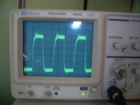
My output has a little ringing (the picture is of my output 50 volt /cm) .
As you can see on the second picture its still ragtag prototyping
The improvised snubber is a disapative rc snubber this improved it a little but its not gone .
Is this ringing any problem ,or is it normal ?
My gates is a nice and tidy square wave ,(unloaded & under load) i have a little ringing but it will be rectified & filtered .
If its not how it should be .
How does youre output signal look like ? and how do i get rid of that oscillation .
I would be very gratefull for youre opinions .
Have a nice eve .
I am building a smps based on a sg3525 13.8 volt in to + & - 310 volt (with middletap) .
It does work although i am cautious with putting more load on (for now).
Let me explain or let the pictures i attached show .
The frequency it runs on is 80 khz , But the rise time is maybe even 15 % of that .
My mosfets (4 x 50n06) get warmer then they should be fully opened .
Now i have 2 suspicions .
A : 13.8 volt might be a little low to fully open my mosfets fast .
B : the sg3525 isn't capable to deliver enough amperage to charge my gate capacity that fast .
When i look around on the internet and here ,i see 2 designs with & without totem pole to drive the mosfets .
Would my risetime improve when i add totem poles drivers ? .
Those designs on this site are straight out of the accu without any voltage doublers so i guess 13.8 volt should do .
Ok that was part 1 of my questions .
Part 2 is this ,since i didnt have any comparison material (i couldn't find any images of this on the web) .
My output has a little ringing (the picture is of my output 50 volt /cm) .
As you can see on the second picture its still ragtag prototyping
The improvised snubber is a disapative rc snubber this improved it a little but its not gone .
Is this ringing any problem ,or is it normal ?
My gates is a nice and tidy square wave ,(unloaded & under load) i have a little ringing but it will be rectified & filtered .
If its not how it should be .
How does youre output signal look like ? and how do i get rid of that oscillation .
I would be very gratefull for youre opinions .
Have a nice eve .
Attachments
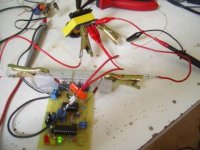
If the first picture shows your actual prototype, you have really a lot to improve in that layout. The transformer should be placed in the PCB near the MOSFETs (no long wires!). Also, an input filter is required to prevent the high frequencies produced when switching from escaping through the 12V supply wiring. Always avoid long wires and current loops with large area when high frequency currents are involved (they produce and radiate lots of RF ringing).
Well, first thing I see thats a problem is all that ringing in the square wave, that should be very little to almost none. Second, is this regulated or non-regulated(if it's reged you need to have a minium load on it).
Could you post a pic of your schematic with current values on it so we may examine.
Could you post a pic of your schematic with current values on it so we may examine.
Thanks for youre advice so far .
Its my first smps so to say .
Well i'm not honest the first 2 were good flamethrowers although those were of a different setup (microcontroller & bridge driver based) .
Today i made 2 little changes .
A : like Eva said i removed the wires to the transformer, this reduced the ringing .
B : I looked into the snubbing and used the formula from the website from Ridley about snubbers .
(those values changed into 100 nF & 4.7 Ohm .
This took away most of the ringing from the switching on (there is a still a little spike though) on switch off moment there remains a little oscilation .
(monday i will make pictures of the scope image) .
Monday i will also make a new circuitboard with the transformer & snubbers on the board .
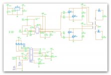
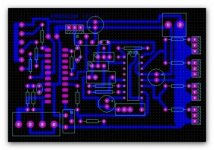
The schematic i builded and the plate i made for it are attached with this post .
About the schematics .
For now i made it without feedback ,unregulated but when everything runs nice i want to remove the potentiometer and connect it to the pin called feedback at the microcontroller .
With pwm duty-cycle variation i want to charge C9 to generate a voltage to variate the duty cycle of the 3525 .
The rest of the schematics speak more or less for itself .
The potentiometers around the microcontroller are for reading the battery voltage & adjusting startvalue of the pwm .
For now it only checks the temperature and reads battery voltage .
(temperature & low battery control the shutdown pin of the sg 3525)
The circuitboard has 1 mistake (ground towards the oscilator resistors,capacitor was forgotten)
Further was the purpose of this plate to try the powersupply and be able to test & improve the software .
Like i said monday i will make a new plate with the whole smps on the plate ,if you see any dont do's in how i made the setup please tell me .
I'm very gratefull for youre comments .
Like i said its my first smps ,and as i always say you learn by doing 🙂
Its my first smps so to say .
Well i'm not honest the first 2 were good flamethrowers although those were of a different setup (microcontroller & bridge driver based) .
Today i made 2 little changes .
A : like Eva said i removed the wires to the transformer, this reduced the ringing .
B : I looked into the snubbing and used the formula from the website from Ridley about snubbers .
(those values changed into 100 nF & 4.7 Ohm .
This took away most of the ringing from the switching on (there is a still a little spike though) on switch off moment there remains a little oscilation .
(monday i will make pictures of the scope image) .
Monday i will also make a new circuitboard with the transformer & snubbers on the board .
The schematic i builded and the plate i made for it are attached with this post .
About the schematics .
For now i made it without feedback ,unregulated but when everything runs nice i want to remove the potentiometer and connect it to the pin called feedback at the microcontroller .
With pwm duty-cycle variation i want to charge C9 to generate a voltage to variate the duty cycle of the 3525 .
The rest of the schematics speak more or less for itself .
The potentiometers around the microcontroller are for reading the battery voltage & adjusting startvalue of the pwm .
For now it only checks the temperature and reads battery voltage .
(temperature & low battery control the shutdown pin of the sg 3525)
The circuitboard has 1 mistake (ground towards the oscilator resistors,capacitor was forgotten)
Further was the purpose of this plate to try the powersupply and be able to test & improve the software .
Like i said monday i will make a new plate with the whole smps on the plate ,if you see any dont do's in how i made the setup please tell me .
I'm very gratefull for youre comments .
Like i said its my first smps ,and as i always say you learn by doing 🙂
Attachments
Adnancoskun said:ý made many SMPS with SG 3525, all of them very good, you can look at our web page, www.eproje.com
Where is the "Dutch" or "English" button can't read the website
Member
Joined 2002
Jaac said:
Where is the "Dutch" or "English" button can't read the website
Very nice website, im glad to see another person working on the F4 project, you have the exact same heatsinks as me and basically the same layout that im planning.
Jase
sorry, forgive me, that site is Turkish language, but if you want, ý can help to you,you can ask everything
Last 2 days i spended a lot of time on theory and made a few changes in the snubbers .
My switch on is now totaly free of ringing ,but my switch off still shows a little spike & oscilation as the picture will show .
Like Eva said i made all the traces carrying higher frequency's short .
This took away some of the ringing .
And concerning the things Ifrythings asked .
I dont have exact ampere readings yet .
The transformer i made is a 3c90 core with etd 44 bobbin .
2 x 5 windings primary ,high voltage secundary is +_ 2 x 80 windings (centertapped) and 2 times 6 windings (for gate voltages on the secundary side)
The eventual goal is 3 to 400 VA on the high voltage windings .
But for now in the testing and developing (read learning phase)i test with normal 220 volt lightbulbs .
After reading a few chapters in Switching Power Supply Design 2ed written by A.Pressman i calculated my way through the whole gatedrive circuit & snubbers and that solved all the ringing (at least on the top) .
Maybe someone here knows a better solution then the dissapative snubbers ,as it is now the snubbers dissapate even with the small load (40 watt) i use for testing a few watt .
Another thing i would like to ask is how do i get rid of that switch off peak .
The pictures i posted are like before measured with a 40 watt load on the high voltage out .
Like the last time the scope is set on 50 volt/cm .
Is there any book that you can advise me about push-pull topology or the elektro magnetics involved.
(when i have to be honest i always hated the elektro magnetics at school )
🙄 (now i regret that)
The new circuitboard got overdeveloped unfortunatly ,i will have to get new photoplate .
Layout and everything is ready but i had a lil accident developing :S (but at least i still have my eyebrows)
As always i will be very happy with you're remarks and advices .
Attachments

- Status
- Not open for further replies.
- Home
- Amplifiers
- Power Supplies
- sg3525 smps signal pictures