Hi everybody, I'm new to this forum.
I have an Electrovoice 81PMX power mixer that was blowing fuses. The previous owner had replaced all the power FETs and did a pretty crappy job. I put in new ones (IRF640 and IRF9640) and now it's OK, but there is a note on the power amp board saying I need to adjust the bias when replacing FETs. What exactly am I looking for when I adjust it?
I'm not used to high power stuff and my FET theory is shaky.
Can anyonelet me know how to adjust this properly?
Thanks!
first, attach a dc voltmeter across the emitter resistors and bring up the amp on a variac. if the voltage across the emitter resistors goes over 100mV before you get to full line voltage, shut it down!!!!!
if you are able to get to full line voltage, adjust the bias pot until you get between 10 mV and 20 mV across the emitter resistors. the bias pot is usually near a transistor or diode "stack" (usually a red blob shaped thing in a clip that screws to the heat sink). you will also want to adjust the offset by attaching a voltmeter across the speaker terminals and adjusting the offset pot (usually near the amp board input cable) until you have 10mV or less across the speaker terminals.
if you are able to get to full line voltage, adjust the bias pot until you get between 10 mV and 20 mV across the emitter resistors. the bias pot is usually near a transistor or diode "stack" (usually a red blob shaped thing in a clip that screws to the heat sink). you will also want to adjust the offset by attaching a voltmeter across the speaker terminals and adjusting the offset pot (usually near the amp board input cable) until you have 10mV or less across the speaker terminals.
Thanks guys, but as I was adjusting the bias, I would see the voltage swing up to 15mV or so, and then right back to 0. I thought I needed to increase a bit more, but then true to Murphy's law, all four PNP FET's blew (these are double the price of the NPNs).
Before I try this again, I'd like to figure out why this happened. I measured across the source resistors (they are 0.33ohm, 2W). Could using a magnetic screwdriver affect it? I can't think of anything else. Help?
Before I try this again, I'd like to figure out why this happened. I measured across the source resistors (they are 0.33ohm, 2W). Could using a magnetic screwdriver affect it? I can't think of anything else. Help?
Hi,
are the output devices set up as source followers
or
as CFPs?
I think the source follower requires more bias to reduce crossover distortion.
I wonder if the amp is actually a quasi complementary set-up to eliminate the need for expensive 9640?
How many pairs are fitted to each channel of the output stage?
Any chance of posting a schematic?
I don't have a schematic. There is an initial BJT NPN/PNP pair, then four pairs of 640/9640. I'm not used to the FET amps so much. Also, I was measuring the bias with no signal applied. Do I need a signal? I have a sine wave source.
Hi,
output bias and output offset are both measured and re-set, if necessary, with the input shorted to ground and with the output open circuit (=no load).
4pair of 120W devices should be able to give 150W to 200W of output power if designed to be reliable.
15mV on Vre is tiny if measured correctly.
There appears to be another fault.
You need a search out a schematic.
bdeko said:Thanks guys, but as I was adjusting the bias, I would see the voltage swing up to 15mV or so, and then right back to 0. I thought I needed to increase a bit more, but then true to Murphy's law, all four PNP FET's blew (these are double the price of the NPNs).
Before I try this again, I'd like to figure out why this happened. Help?
And this is why I use a light bulb (60w's or so) in series with the mains when I first fire up or change settings. It's cheap current limiting and saves you many expensive parts. Also check or replace the bias pot, if it has a dead spot (aka open area) this could kill the amp.
AndrewT
I wonder if the amp is actually a quasi complementary set-up to eliminate the need for expensive 9640?
That could be very possible.
Thats easy to check, if (-) rail goes to center leg of fet thens it's complementary, but if it goes to the source then it's quasi complementary (all N-channel Fets) (Gate will be a few 3-4 volts higher the the (-) rail)
It definitely is complementary.
What do you mean about the light bulb in series with the mains? Where exactly do you wire the bulb? I'm curious 'cause I really don't want another $40 going up in smoke.
The bias pot is OK; checked it with a Fluke multimeter and turned it slow - no dead spots.
What do you mean about the light bulb in series with the mains? Where exactly do you wire the bulb? I'm curious 'cause I really don't want another $40 going up in smoke.
The bias pot is OK; checked it with a Fluke multimeter and turned it slow - no dead spots.
I have a light bulb with wires and holder straped onto a chunk of wood and on the wires are aligater clips.
As for were to put it, I usually pull out the fuse and put clip the leads onto the fuse holder, then the bulb is in series and stuff can't get hurt.
DO NOT use a high watage like, or it's usless, I use a 60w bulb.
you have to use a Incandescent light bulb too, the mini fourecents don't work.
Have you checked the bias transistor? for shorts? for leaky junctions? pull it out of circuit for testing.
Hi,
I can see you have not searched for light bulb yet.
It would be safer to straddle the light bulb holder with a plug top and a socket outlet. Then it can be used on all mains operated equipment.
I can see you have not searched for light bulb yet.
It would be safer to straddle the light bulb holder with a plug top and a socket outlet. Then it can be used on all mains operated equipment.
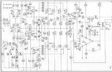
Hi, here I have a schematic that is identical as far as I've checked.
I also have included the bias procedure (it references the wrong resistor numbers, but I've figured that out). So from what I understand, when I turn up the bias, I want all the voltages measured across all the power resistors to be roughly equal (that will satisfy the equation given).
My problem is that the first N FET and the last P FET consistently are way higher than the others. So when I turn up the bias so that the first N FET is 10mV, the last P FET will be ~8mV and everything else is ~1mV or less. The procedure tells me to replace those FETs with a higher reading, but I've done that a couple of times with the same results. What else could be causing this?
The amp is working right now, but in this state I will get massive distortion if I crank it up, correct?
Thanks,
Brian
Attachments
Hi,
measuring the 8 Vre is allowing you to compare the bias currents through each device.
The difference in readings is telling you that the devices are not well matched.
The 4devices in each half should be selected to be a close match to each other. Changing just one is unlikely to ever chance upon a match.
If you turn up the bias until the highest Vre=20mV what do the others read?
The danger from running unmatched devices is that a few or just one will run considerably hotter than it's partners and that hot device will be closer to it's SOAR limit. This device may eventually fail, particularly if you allow the heatsink to get hot due to high ambient temperatures or low impedance loading or simply very loud music.
When the highest is 20mV, the next is ~16, then they are all under 10, except for one NFET that is 0.1mV.
I think I'm in trouble as far as matching goes... I didn't realize they all had to be matched, and now I'm out about $75 with a whack of unmatched FETs.
Crap.
Any place to buy FETs pre-matched? I've seen some for sale here, but not what I need.
I think I'm in trouble as far as matching goes... I didn't realize they all had to be matched, and now I'm out about $75 with a whack of unmatched FETs.
Crap.
Any place to buy FETs pre-matched? I've seen some for sale here, but not what I need.
Hi,
judging by the comments made by Anatech re his compatriates, you have done no worse than many electronics technicians.
It may be that you can get away with what you have done.
But I suggest, you keep this amp cool or cold, by going easy on the volume control and accept that if you push it, it may become unreliable.
If the schematic is correst, as far as i can tell, this amp has no bias thermal compensation, considering it is using vertical MOSFETs, this is at least a design flaw, and at worst criminaly irresponsible. The bias current will increase as the temerature rises, and looking at the datasheet fior the IRF devices, it may even be fatal.
Secondly, are all your FETs the same manufacturer? At the very least, all the 640s and all all the 9640 should be the same manufacturer. Thirdly, have you checked that all the 0.33 ohm resistors are actually still 0.33 ohm, and not open circuit? (that 0.1mV across one of them is very suspicious).
Secondly, are all your FETs the same manufacturer? At the very least, all the 640s and all all the 9640 should be the same manufacturer. Thirdly, have you checked that all the 0.33 ohm resistors are actually still 0.33 ohm, and not open circuit? (that 0.1mV across one of them is very suspicious).
- Status
- Not open for further replies.
- Home
- Amplifiers
- Solid State
- setting bias for power FETs?