Hi Everyone – hope someone can help me out here..
I have a Selmer Treble n Bass 50w SV guitar amplifier. Bought as ‘for parts or not working’. I diagnosed faulty power/standby switches, fuse blown, and generally needed a clean up – contacts etc.. I repaired anything obvious before attempting to switch on, such as corroded lugs etc..
It now powers up OK. No nasty noises, microphonics, ringing etc, but only the ‘normal’ (treble) channel is operating as it should. The ‘bass’ channel is producing a VERY low signal, which is consistent, regardless of where the controls are set on the front panel. I mean REALLY REALLY faint, but clean-sounding.
I’m a qualified electrician, so I’m safe to take readings at various points on the circuit, but am not experienced enough in electronics to diagnose this one….
All resistance values of components (including potentiometers) check out fine from the input stage right through to where both channels eventually meet ahead of the ‘echo’ send/return stage. I can’t measure capacitance values, though (I don’t have a capacitance meter).
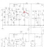
The only odd reading is this: the voltage at one of the anodes of the EC883 (shown on the attached jpegs), is up towards 300 volts dc, where as it should be around half of that. All other anode voltages are as they should be – around the 140 mark..
This is pin 1 of the EC883, where pin 2 (grid) is the ‘return’ from the volume/tone controls stage..
I have obviously switched valves around, checked continuity of all conductors, checked all connections around the input stage etc..
It’s as though the anode/cathode of this second triode is an open circuit, or the valve simply isn’t there, bringing the voltage at the anode up to supply rail????
Any help greatly appreciated. I’d love the satisfaction of sorting problem myself (with someone’s help, obviously…!)
Cheers. Gary
I have a Selmer Treble n Bass 50w SV guitar amplifier. Bought as ‘for parts or not working’. I diagnosed faulty power/standby switches, fuse blown, and generally needed a clean up – contacts etc.. I repaired anything obvious before attempting to switch on, such as corroded lugs etc..
It now powers up OK. No nasty noises, microphonics, ringing etc, but only the ‘normal’ (treble) channel is operating as it should. The ‘bass’ channel is producing a VERY low signal, which is consistent, regardless of where the controls are set on the front panel. I mean REALLY REALLY faint, but clean-sounding.
I’m a qualified electrician, so I’m safe to take readings at various points on the circuit, but am not experienced enough in electronics to diagnose this one….
All resistance values of components (including potentiometers) check out fine from the input stage right through to where both channels eventually meet ahead of the ‘echo’ send/return stage. I can’t measure capacitance values, though (I don’t have a capacitance meter).
The only odd reading is this: the voltage at one of the anodes of the EC883 (shown on the attached jpegs), is up towards 300 volts dc, where as it should be around half of that. All other anode voltages are as they should be – around the 140 mark..
This is pin 1 of the EC883, where pin 2 (grid) is the ‘return’ from the volume/tone controls stage..
I have obviously switched valves around, checked continuity of all conductors, checked all connections around the input stage etc..
It’s as though the anode/cathode of this second triode is an open circuit, or the valve simply isn’t there, bringing the voltage at the anode up to supply rail????
Any help greatly appreciated. I’d love the satisfaction of sorting problem myself (with someone’s help, obviously…!)
Cheers. Gary
Attachments
Thanks Nigel, I'll check later when my test meter comes back..it's out in the car. I'm guessing cathode should be low voltage as per circuit diagram? As for grid, dunno. I'm no expert, but learning fast!
Thanks Nigel, I'll check later when my test meter comes back..it's out in the car. I'm guessing cathode should be low voltage as per circuit diagram? As for grid, dunno. I'm no expert, but learning fast!
Yes, the cathode should be low as per the diagram, and the grid should be zero volts, or occasionally slightly negative.
As I see it there are two possibilities? (as you've swapped valves):
1) The cathode resistor is O/C - cathode will read high.
2) The valve base is faulty (so there's no connection to the resistor), so it will have zero volts across it.
A third, far more unlikely scenario, is that the grid is getting a negative voltage from somewhere, turning the valve off - so negative grid (more than slightly) and low (or no) voltage on the cathode.
Valves are very crude and simple, there's not much to fault finding with them.
Thanks again Nigel! I'll check out all your suggestions. I'm sure I've tested a couple of those already, but will make double sure. Really want to get the bass channel working - had a MkIII TnB a couple years ago, and the bass channel was sweet! Thanks for the encouragement. Old dog learning new (but very interesting) tricks, here!
When the plate voltage is way up to the supply voltage, you are correct, the tube is not conducting - acting as open. I would also expect zero volts across the cathode resistor - zero current means zero volts.
Look closely at the heaters, are BOTH heaters glowing in that tube? If your heaters are wired for 6v as almost all are, the link between pins 4 and 5 may be broken, or pin 4 or 5 may itself be broken. And if the heater is dark on the one side, it won;t conduct. Or even just a sprung loose socket pin. If you find a dark heater side it should be easy enough to determine why.
CErtainly open cathode resistor is possible, as is open path to ground. it is not sufficient for the cathode resistor to be intact and on value, it must also complete its circuit, so don't measure the 2.2k at the resistor, measure for 2.2k between pin 3 of the tube and the chassis ground. That will verify all connections as well as value.
Thanks for the info and taking time to post, Enzo! I'll investigate further today hopefully... Great advice all around, here. Thanks again, guys.
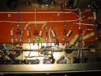
OK....this is getting confusing! I've replaced the valves with newer ones out of my fender amp, so I can see inside them properly to see what's glowing. As Enzo suggested, only one side of the bass channel valve is glowing - both sides glowing on treble channel valve. Switched over, and same result, so there's the problem - heater on one side not heating/glowing..BUT there appears to be no problem with connections, though. Pins 4 and 5 of the valve base show perfect continuity (tested from the valve side), so they are nicely connected, and nicely seated - nothing's loose, it's all nice and tight. I've measured grid and cathode voltages, and they're both at zero. Also tested from pin 3 to ground, and result 2.2k, so that's OK. Any other reason why heater wouldn't heat/glow? I'm really confused, now! I'm also guessing heater would be AC voltage - it seems to get its supply direct from transformer, rather than via rectifier..
Hoooray! Sorted... Even though continuity checked out between pins 4 and 5, pin 4 obviously somehow wasn't making contact with the valve.. I inserted a temporary link across from the valve side, and hey presto! Bass channel working, and both sides of the valve glowing beautifully!!!! Thank you so much for valuable help and encouragement, guys! I'm ever-thankful
Did you just resolder pins 4 and 5, regardless of how they looked?
Look down into the dead pin from above. Is the female pin spread open or otherwise bent?
And sometimes:
the socket pin has two parts, the top side is the female structure that grips the tube pin. The bottom side is a solder tab for wire connections. RARELY, but now and then, the pin will break in half in the middle. The bottom solder tab is still soldered to the wiring, and the female still grips the tube pin, but the two halves are broken apart and no circuit is made.
Hi again Enzo. The female pin upon very close inspection looks slightly more 'yellow' and tarnished than the others, and maybe slightly more spread open.. I think it just isn't conducting well enough to operate the heater. Pin to solder joint shows closed circuit, but that's with my test meter probes, and not ECC83 pins..These bases seem cheap enough to replace, so that's my next move.. probably replace them all while I'm at it. Thanks for sharing your knowledge - I'm really chuffed to get to a solution with everyone's help - very satisfying!
Somewhat late to this thread but I've just scored one of these amps very cheaply. It works but there is a lot of mains hum, so first jobs will be:
- General clean up and familiarisation with the schematic, and where all the components are;
- Test valves and replace as necessary;
- Replace filter caps - probably degraded and thus responsible for AC breakthrough; and
- Replace mains cable, which is through to the basic installation where it enters the chassis - may even cut a hole for an IEC inlet, but that would be hard work through steel plate!
An externally hosted image should be here but it was not working when we last tested it.
- Status
- Not open for further replies.
- Home
- Live Sound
- Instruments and Amps
- Selmer TnB 50w SV problem with Bass Channel