As title is saying.....I want to learn something more than just making a class D amplifier.I made a lot of modules in my life from few watts to few KW.Synch is easy with non self oscilating amplifiers.I tried to synch two modules which are self oscilating and i couldnt do that to be good.Sound becomes distorted,specialy at low levels of output.High power is almost good.I tried clock (50%) + R+C to main cap on integrator (on both with independant R+C).....and few other possible way but its almost the same.If i get to proper synch sound is bad.....if i make small missmatch in synch sound is perfect.I will be very thankfull if someone want to talk about this.Please do not go in to concepts and theory lets be practical.I have equipment and can test whatever i like....so lets test something.My amp concept is simplest possible....op amp input to comparator and post filter feedback is going in to inverting input....simplest concept.If there is someone who made this please send me some link to video or something so we can discuss all further.Thank you all in advance.
Last edited:
If you use a common clock, distortion will arise due to harmonic noise beating between channels. All class D amplifiers have their own oscillator, some won't oscillate without a load, because they use positive feedback from the load and some vary the frequency dependant on the load. As far as I am aware, none are crystal controlled.
... or the ones who made it are just wondering what might happen in your design.
Any measurements which would quantify what you describe as 'sound becomes distorted' or as 'almost good'?
Are you talking about THD levels of 0.0xxx% or about more obvious distortions above 1%?
Or is there something strange becoming visible on the oscilloscope?
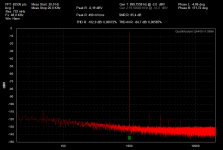
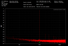
So far I only made one amp which offers self oscillating operation and also clocked mode. In this particular design the clocked mode indeed shows higher distortions, however still on a very moderate level. And different from your experience the distortion at low levels remains close to my measurement limits and only worsens with larger signals.
The related design is the +/-40V version of the LiteAmp, which you can find in posting #400 of this thread.
http://www.diyaudio.com/forums/class-d/255046-systemd-liteamp-40.htm
Note: If you are interested in the higher voltage versions make sure to use the corrected BOMs from posting #401 (however only the +/-40V version is tested with the clocked option)
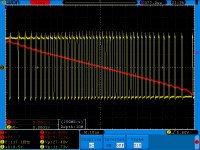
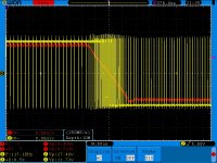
The first two attached pictures show the results from self oscillating operation.
Picture 1: 1W into 4R
Picture 4: 10W into 4R
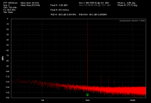
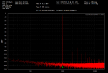
Third and fourth picture are in clocked mode.
Picture 3: 1W into 4R, clocked
Picture 4: 10W into 4R, clocked
Any measurements which would quantify what you describe as 'sound becomes distorted' or as 'almost good'?
Are you talking about THD levels of 0.0xxx% or about more obvious distortions above 1%?
Or is there something strange becoming visible on the oscilloscope?
So far I only made one amp which offers self oscillating operation and also clocked mode. In this particular design the clocked mode indeed shows higher distortions, however still on a very moderate level. And different from your experience the distortion at low levels remains close to my measurement limits and only worsens with larger signals.
The related design is the +/-40V version of the LiteAmp, which you can find in posting #400 of this thread.
http://www.diyaudio.com/forums/class-d/255046-systemd-liteamp-40.htm
Note: If you are interested in the higher voltage versions make sure to use the corrected BOMs from posting #401 (however only the +/-40V version is tested with the clocked option)
The first two attached pictures show the results from self oscillating operation.
Picture 1: 1W into 4R
Picture 4: 10W into 4R
Third and fourth picture are in clocked mode.
Picture 3: 1W into 4R, clocked
Picture 4: 10W into 4R, clocked
Attachments
Last edited:
"As far as I am aware, none are crystal controlled." Thats what i concluded too so far.I want to make BD modulation (or filter-less).And i want to try that with self oscilating amplifier modules.So far i made that easy with constant switching frequency and it works like a charm.But this self oscilating topology i couldnt make to work good.If i am able to hear distorsion then its high.I didnt measure anything....no reason for that if its not good.I tried various R+C for input clock....there are few slight differences but,if distorsion is lower there is intermodulation sound from clock frequency.....On other side if all is clear and there is no noise on low levels and without signal then on higher output levels i have cracking kind of modulation.Its not loud but is present.Without modulation i have clear output and no audible hum or anything simmilar without signal on input.
Last edited:
I didnt measure anything....no reason for that if its not good
THD measurements are of low value for hunting such massive issues, correct.
However oscillscope examinations of the modulator and swichting stage
would be a natural R&D approach to find and correct obstacles like described from you.
Trying to understand from the sound what's wrong in the circuit often is difficult - still sometimes possible.
Crackling sound often is caused by collapsing/intermitting carrier and/or oscillation.
I agree about all what you said.Crackling sound is coming from wrong modulation of the carier.....if i disconect signal generator its all clear.I dont have humps-bumps and huge issues.....just distorted sound.Very distorted.Is there any schematic where BD modulation is done and works but where all is made with analog components without MCUs or "all in chip" solution?
I need opinion about one thing named "phase shift".Is it possible to make amplifier which will have for example phase shift of 10deg on all input frequencies......so to have locked phase shift and linear output responce from 5Hz to 70KHz on small power output like 2Vpp and on speaker as load (complete box with all three ranges-speakers in it) ?
Never mind....i have big imagination,and i am asking to much.I almost made what i described.I think that if i could then anyone can and i expected a discussion.But i was wrong.
Anyway,i want to share some thoughts with you guys."Problem" with self oscilating amp is in its sigma delta modulation.....which means frequency and duty cycle together are changing during the time when input AC voltage is applied(on modulation).This (for now) looks impossible to synch becouse we have to know "middle point" of each pulse to make synch pulse from which we can generate oposite size pulse (for second channel) , and frequency is changing ultra fast.With constant clock thats easy as i mentioned before,we need simply to invert triangle wave.Here if we apply input clock ,and this i tried, we are blocking natural sigma delta modulation and amp is forced to do something which is not good for sound.
This can be done with some tehnique pulse to pulse ....... find-center-lock system or with some simetry related to MODULATED triangle.Still any of that two requires ultra high speed circuitry.
Also one more thing .... i am talking here (and we all i think) about integrator input type self oscilating class d amplifier.Does anyone here made digital chip (D fli-flop or other logic) based self oscilating class d amplifier which has sigma delta modulation?Maybe that concept is easyer to synch.I didnt try to do a researsh on that and if there is something that you guys know and want to share i will be very thankfull becouse i will test it and do all tests to be open source if schematic is good.I dont care if schematic is for 1W i will make and test it.
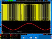
I will upload here a photo to show how sigma delta look like on one of my amplifiers.I dont need schematics for amplifiers doing this what i am talking about.I am interested to learn to how to make this as working concept for 1W amplifier which means to improve what i/we already know about all this.
This can be done with some tehnique pulse to pulse ....... find-center-lock system or with some simetry related to MODULATED triangle.Still any of that two requires ultra high speed circuitry.
Also one more thing .... i am talking here (and we all i think) about integrator input type self oscilating class d amplifier.Does anyone here made digital chip (D fli-flop or other logic) based self oscilating class d amplifier which has sigma delta modulation?Maybe that concept is easyer to synch.I didnt try to do a researsh on that and if there is something that you guys know and want to share i will be very thankfull becouse i will test it and do all tests to be open source if schematic is good.I dont care if schematic is for 1W i will make and test it.
I will upload here a photo to show how sigma delta look like on one of my amplifiers.I dont need schematics for amplifiers doing this what i am talking about.I am interested to learn to how to make this as working concept for 1W amplifier which means to improve what i/we already know about all this.
Attachments
I dont have humps-bumps and huge issues.....just distorted sound.Very distorted.
Very distorted sound is a huge issue.
Is there any schematic where BD modulation is done and works but where all is made with analog components without MCUs or "all in chip" solution?
BD modulation is very simple.

Can be done in practice many ways. But what is the relevance to synchronising?
Is it possible to make amplifier which will have for example phase shift of 10deg on all input frequencies
Yes. But not easy, and perfectly pointless. I can't see any relevance here either.
integrator input type self oscilating class d amplifier.
Is it really a type of ClassD? I don't think so. Many different ClassD amps can have integrator on its input. Basically all of them.
Please do not go in to concepts and theory
You can't swim without being wet. You seems want to change the rules without get to know them. This is why you don't get more answer, despite many people experimented with synchronising.
Engineers measure. Discussing this topic without both theory and a specific circuit and measurements seems to be a waste of time.
I'm not pride, but once I used synchronisation in order to avoid some interference between 2 channels. It introduced some distortion (not really low, about 0.1 %), but the users didn't notice.

2 UcDs, outputs coupled by a 15 nF capacitor.
Some distortion is always unavoidable. The right question is: how much, and how to lower.
The most important rule: injected signal must be free of steps and ringing.
Last edited:

I agree about distorted sound,but i have it only when i try to synch which is same as you expirienced.Single module works perfect.
BD modulation is easy to make,and i forgot to ask about BD modulation made with self oscilating modules.
If you checked pictures that i uploaded in my previous post you can easy see that its D class amplifier.
When i said that i dont want to go to deep theory i meant to say that i dont need discussion about basic concepts but some deeper look in to the topic.I should write better and describe better what i wanted to say.Thank you for pointing to this.
Now about the topic....I want to keep Delta Sigma modulation and have two modules synchronized.Simply i like when frequency goes down becouse efficiency goes up.I made many d class integrated solutions.Globaly i dont have issue with making a good amp (half bridge or full bridge output) i just tried to make synch that i described here and i found it to be very chalenging.....and there we go.
Point of making synch is not small thing.First of all output filter can be realised to have way less losses,emi suppresion is easyer and pveral efficiency is higher (in relation of what i just described).From what i tried to me it looks that completely new approach is needed for solving this puzzle and it is a big chalenge too.
Thank you for replay Pafi.
Point of making synch is not small thing.First of all output filter can be realised to have way less losses,
How synchronisation makes filter loss lower? Do you think if you synchronise 2 amps, tie them to bridge, then they will work automatically with the same carrier phase and you can make a filter like in case of Class BD? Let's see: post filter feedback self-oscillating type will obviously never work this way, since your filter don't pass anything from the carrier. Pre-filter feedback is not this trivial to analise, but I can't imagine any way that enable self-oscillation and synchronous operation. If you synchronise it to an external source, then it is not self-oscillating anymore by definition. If you synchronise them together, then you will get phase problems.
Maybe if you generate an external, frequency modulated clock that varies the same way as natural oscillation, and you use it to synchronise the 2 amplifiers, then maybe you get a bridgeable amplifier that behave similarly to a hypothetical self-oscillating Class BD, but I'd rather say it will still not work as you expect.
Syncronisation can have an achievable reason: avoiding idle interference. This can be done with low level of coupling, therefore with low distortion. But it will not run synchronised when you apply different modulation signal. If you want to go further with coupling, and maintain strict phase and frequency lock, then either the self-oscillation will be destroyed, or the lock will be broken, and in that point strong distortion is introduced. These cases are not the same.
Syncronisation is not a single phenomenon, there are different levels and aims. You have to decide what is your goal and check if it is not incompatible to the other requirements. Be specific!
Sigma-delta modulation is also not a single phenomenon in practice, but basically not synchronisable.
Yes i think that BD filter scheme will work in this case.Post filter feedback is for audio band only (thats how i learned) so it should work too for single module) and has nothing with carier.Diferencial feedback (pre filter and post filter should be also a working solution).I tested this about feedback and i can confirm that it works.Kind of synch with external source is OK only when there is no input voltage....so 50% output is in phase.But only then.Soon the modulation is started if synch voltage/current are high there will be distorsion.....if its not then synch is OF and there is no BD scheme on output (thats what i achieved with my modules).
"Maybe if you generate an external, frequency modulated clock that varies the same way as natural oscillation, and you use it to synchronise the 2 amplifiers, then maybe you get a bridgeable amplifier that behave similarly to a hypothetical self-oscillating Class BD, but I'd rather say it will still not work as you expect. "
Same thoughts here.This is exactly what i am working on right now. Still this is BIG chess game to solve.Once you try you will understand.Each pwm has its own gain.Theoreticaly is possible to make two identical PWM sections with same gain.....reference PWM (clock) should behave same but from here there are to many "what can go wrong" options.
To be very specific i want to make sigma delta self oscilating bridged amp with fully synch outputs when on idle they are in absolute phase and perform BD modulation scheme.
Still,if there is no chalenge there is no fun.I have a lot of fun here,as you can notice.So far i decided to redesign best design that i have to achieve what we are discussing about.
"Maybe if you generate an external, frequency modulated clock that varies the same way as natural oscillation, and you use it to synchronise the 2 amplifiers, then maybe you get a bridgeable amplifier that behave similarly to a hypothetical self-oscillating Class BD, but I'd rather say it will still not work as you expect. "
Same thoughts here.This is exactly what i am working on right now.
Still this is BIG chess game to solve.Once you try you will understand.Each pwm has its own gain.Theoreticaly is possible to make two identical PWM sections with same gain.....reference PWM (clock) should behave same but from here there are to many "what can go wrong" options.To be very specific i want to make sigma delta self oscilating bridged amp with fully synch outputs when on idle they are in absolute phase and perform BD modulation scheme.
Still,if there is no chalenge there is no fun.I have a lot of fun here,as you can notice.So far i decided to redesign best design that i have to achieve what we are discussing about.
Yes i think that BD filter scheme will work in this case.
Which case?
Post filter feedback is for audio band only (thats how i learned)
Wrong. In case of self-oscillating ClassD feedback is integral part of the oscillator, and exactly this is the reason why feedback can be more effective than one of a clocked design (where carrier must be supressed in the loop, together with the other high freq components). And a designer should not learn this kind of knowledge. A designer must analyse this. It's not a written fact that can be learnt, it's the summary of understanding.
Still this is BIG chess game to solve.Once you try you will understand.
I've already understood it.
Each pwm has its own gain.Theoreticaly is possible to make two identical PWM sections with same gain.....reference PWM (clock) should behave same but from here there are to many "what can go wrong" options.
Identical PWM? Yes, it can be done. But there are 2 requirements: same phase for "clock", opposite phase for audio signal. This means the channels must not work identically. This is not a problem if you use clock, but then this will not be a self-oscillating design. If you really want to maintain self-oscillation and BD modulation the same time, then you have to figure out such a feedback (matrix) loop topology that is anti-symmetrical for the modulating signal and symmetrical for the carrier. For the first time it seemed to be impossible for me, but now I realised it is possible. I'm working on this now, and the simulation is promising.


To make it clear: the channels are synchronised together, not to an external source. (That is a wrong way, however can be done, but inferior in terms of quality.)
To be specific: I'm designing a post and pre-filter, matrix feedback, true phase-shift self-oscillating, bridged amplifier. The pre-filter feedback is really neccessary only in case of the efficient, common mode filter, otherwise post-filter feedback also has a chance to work correctly, and actually this is the first I'm trying.
I believe this works, but I'm not convinced it's better than a clocked ClassBD, because a clocked ClassBD has a doubled effective switching freq regarding to the feedback stability, while self-oscillating amp has to be designed for the real switching freq. They are probably the same both in quality and in issues. 2 differences I see: the clocked design can be synchronised to other amplifiers, but the self-oscillating design can be more insensitive to complex load.
Update: extremely sensitive to delay mismatch.
Last edited:
It will work in case where two sigma delta amps are synchronized and works together.
I was talking about post filter feedback and i didnt think,you are right 100%.
I like how you are thinking.You are right about the way how it should go.Channels need synch between them so external clock can be removed from equation.Phase shift of the carier is a huge issue.Once you make good synch that will lock.Delay missmatch should be zero of course.This means very high level of understanding and knowledge to be done,specially for high power.
Its worth of trying becouse this BD in relation to clocked will be ultra efficient.I am working on very similar concept here.Soon when there is a progress i will upload more info.At this moment we are on exact same page.
...then you have to figure out such a feedback (matrix) loop topology that is anti-symmetrical for the modulating signal and symmetrical for the carrier. For the first time it seemed to be impossible for me, but now I realised it is possible. I'm working on this now, and the simulation is promising.
🙂
Nice idea!

Definitely inspiring.
Keeping fingers crossed that you manage to handle tolerances and the impact of the second sync effect caused by the load. Obviously the load can have a wide complex range of realistic values. IMHO the more post filter loop gain you apply, the more this second sync effect will impact.
Most likely a pre filter feedback structure will be less suffering from this.
I guess a mixed pre and post filter feedback should allow to weight the parameters in the necessary way.
Thank you!
The load also has a sync effect, but fortunately it helps. Without load the carrier phase difference is extremely sensitive to delay mismatch, but if I increase load sync with a parallel 330 nF (the same amount as the LPF), it becomes much better, and if I replace it to 330nF+2ohm in series, then it becomes almost insensitive to mismatches (both for inductance and delay). I tried it even without the sync capacitors, but they are still needed, however only 10% of the normal feedback was enough to maintain satisfactory phase balance. Next step is trying in real life. Then to modify feedback to pre-filter.
The load also has a sync effect, but fortunately it helps. Without load the carrier phase difference is extremely sensitive to delay mismatch, but if I increase load sync with a parallel 330 nF (the same amount as the LPF), it becomes much better, and if I replace it to 330nF+2ohm in series, then it becomes almost insensitive to mismatches (both for inductance and delay). I tried it even without the sync capacitors, but they are still needed, however only 10% of the normal feedback was enough to maintain satisfactory phase balance. Next step is trying in real life. Then to modify feedback to pre-filter.
Thank you!
The load also has a sync effect, but fortunately it helps. Without load the carrier phase difference is extremely sensitive to delay mismatch, but if I increase load sync with a parallel 330 nF (the same amount as the LPF), it becomes much better, and if I replace it to 330nF+2ohm in series, then it becomes almost insensitive to mismatches (both for inductance and delay). I tried it even without the sync capacitors, but they are still needed, however only 10% of the normal feedback was enough to maintain satisfactory phase balance. Next step is trying in real life. Then to modify feedback to pre-filter.
I am also working on Tri level BD mode modulation post filter feedback but with single supply, I have managed to lock the sync with coupled integrator capacitor at input and also at the output. So far the results are good but in multi channel application, I have found one needs LC filtering of rails to eliminate the noise and whistles happening due to the beat frequency oscillation. Also how you layout the modulator is also responsible to keep the noise to bare minimum.
- Status
- Not open for further replies.
- Home
- Amplifiers
- Class D
- Self oscilating Class D synchronization