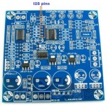
I have an AK4396 DAC board which already has an SPDIF input.
But I want to add an external board with an USB input. Output from this board is I2S.
As there's four I2S signals coming from the CS8416 where the coaxial goes in, I need to add a source selector to choose between those two groups.
One way seems to be using a 74HC125 to select between them, or use two reed relays for the same purpose. I also need to have some mute on the signals when I switch them.
I never built a switch for digital signals, so this is unknown territory for me. It has to be small and simple too.
In my mind, using a toggle switch to energize or not the relay seems the simpler way. Is it not?
I've done it with Reed Relays, works a treat.
Just be carefull routing the BCK Signal, very susceptible to corruption. I gave it its own Relay and mounted further away from the rest.
Hope this helps,
P.
Just be carefull routing the BCK Signal, very susceptible to corruption. I gave it its own Relay and mounted further away from the rest.
Hope this helps,
P.
I have an AK4396 DAC board which already has an SPDIF input.
But I want to add an external board with an USB input. Output from this board is I2S.
As there's four I2S signals coming from the CS8416 where the coaxial goes in, I need to add a source selector to choose between those two groups.
One way seems to be using a 74HC125 to select between them, or use two reed relays for the same purpose. I also need to have some mute on the signals when I switch them.
I never built a switch for digital signals, so this is unknown territory for me. It has to be small and simple too.
In my mind, using a toggle switch to energize or not the relay seems the simpler way. Is it not?
Just take 5v from usb to control your switch (ic or relay).
I've done it with Reed Relays, works a treat.
Just be carefull routing the BCK Signal, very susceptible to corruption. I gave it its own Relay and mounted further away from the rest.
Hope this helps,
P.
Do you remember the schematic or what reed relays you used?
Just connect the paths to each pin and relay, and then a 3-position toggle to select where the 5 volts go to?
BTW: did you use thin coaxials for each signal? I have told this is a must and might be the reason for the problems you had with BCK.
Last edited:
No reason to mess about with relays and coax (Which I would hope you were terminating correctly?).
Whats wrong with a simple quad 2 input mux (74HC157 or similar?), simple, cheap and will not suffer contact bounce.
Regards, Dan.
Whats wrong with a simple quad 2 input mux (74HC157 or similar?), simple, cheap and will not suffer contact bounce.
Regards, Dan.
No reason to mess about with relays and coax (Which I would hope you were terminating correctly?).
Whats wrong with a simple quad 2 input mux (74HC157 or similar?), simple, cheap and will not suffer contact bounce.
Regards, Dan.
I wouldn't know how to design a selector using it.
Apologies, it was the MCLK that I had trouble with and from my schematic I gave each signal its own relay.
I ended up using fairly thick Coax for the MCLK in from the WM8805 in use which was slightly farther away than the i2S signals from the USB PCB I was using.
All the rest were just a ribbon of wires.............
GND,Signal,GND,Signal......etc etc. But keep these fairly short (max 10cm I'd advise) and series resistors on the I/P side of say 100 OHM for the LRCK, DATA and BCK wouldn't go amiss.
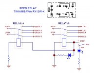
I was only switching between two i2S sources, see the attached schematic.
The Relays were similar to this one..........
DIP05-1C90-BV704 | SPDT Reed Relay, 0.25 A, 5V dc | RS Pro
the ones I used don't seem to be available any longer.
No contact bounce evident and good up to 384kHz Digital signal.
I experimented using an IC to do the job but could not get satisfactory results whereas with the relays, after a bit of re-jigging with the MCLK worked a treat.
Hope this helps,
P.
I ended up using fairly thick Coax for the MCLK in from the WM8805 in use which was slightly farther away than the i2S signals from the USB PCB I was using.
All the rest were just a ribbon of wires.............
GND,Signal,GND,Signal......etc etc. But keep these fairly short (max 10cm I'd advise) and series resistors on the I/P side of say 100 OHM for the LRCK, DATA and BCK wouldn't go amiss.
I was only switching between two i2S sources, see the attached schematic.
The Relays were similar to this one..........
DIP05-1C90-BV704 | SPDT Reed Relay, 0.25 A, 5V dc | RS Pro
the ones I used don't seem to be available any longer.
No contact bounce evident and good up to 384kHz Digital signal.
I experimented using an IC to do the job but could not get satisfactory results whereas with the relays, after a bit of re-jigging with the MCLK worked a treat.
Hope this helps,
P.
Attachments
Nice schematic. It's exactly what I intend to do.
But I should be using two dual reed relays like these:
https://www.fujitsu.com/downloads/MICRO/fcai/relays/ry.pdf
Low priced and good quality:
4 pcs TAKAMISAWA RY12W-K 2C DPDT Signal Relay For Audio
The advice about using thin coaxials for the I2S connections came from a person who has worked a lot with this stuff. Ribbons are fine for testing and else, but coaxials for finishing.
Nice suggestion, but I already have an AK4396 DAC board, with CS8416 receiver on it. I would have to add the USB board anyway, on top of this board.
But this board adds two coaxial inputs, an optical and a plug-in USB board, a selector and an LCD display.
As I am not familiar with these matters, can I plug the I2S output on the side on the four I2S pins I have on my AK4396 board?
But this board adds two coaxial inputs, an optical and a plug-in USB board, a selector and an LCD display.
As I am not familiar with these matters, can I plug the I2S output on the side on the four I2S pins I have on my AK4396 board?
yes, you can but without knowing your current connection and layout around your AK4396 it's hard to judge how to connect those I2S input lines to your DAC chip, unless you already know how to...AK4118 board has clear identification on the output pins so from this side it should be easy...
- Status
- Not open for further replies.
- Home
- Source & Line
- Digital Source
- Selecting sources for I2S