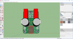
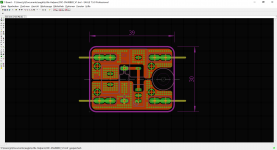
Here two "Little Helpers" boards I´ll order end of next week.
If someone is interested?
JP
If someone is interested?
JP
Attachments
-
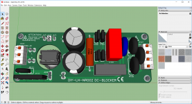
 SMPS-FILTER.png662.2 KB · Views: 566
 -
DIY-LH-NR002_PBA.pdf19.1 KB · Views: 82
-
DIY-LH-NR002_PCB.pdf17.9 KB · Views: 96
-
DIY-LH-NR002_SCH.pdf18.2 KB · Views: 139
-
 DC-BLOCKER_001.png940.1 KB · Views: 567
 -
SMPS-FILTER_BOT.pdf15.3 KB · Views: 99
-
SMPS-FILTER_TOP.pdf14.4 KB · Views: 96
-
SMPS-FILTER_PCB.pdf60.4 KB · Views: 92
-
SMPS-FILTER_SCH.pdf14.5 KB · Views: 150
JP, if you're taking requests it would be great to have a little board to retrofit a three-element CRC snubber near the transformer for PS designs that don't already include that. Part values would come from the popular Quasimodo jig: Simple, no-math transformer snubber using Quasimodo test-jig
BK
BK
This is a prime example of a thread title being totally useless.
 Agree!! Hopefully I've now made it at least a little more meaningful, though I'm not 100% certain on that....
CRC Snubber...
JP
Nice! The trimmer might be a bit superfluous, but doesn't occupy much space if someone doesn't want to populate it. Quick scan of the recommended EPCOS B32529 caps at Mouser doesn't show any parts longer than 7.8mm and all are 5mm LS, so perhaps that overall footprint could be scaled back. MJ's two suggested values are ~3mm wide. Only my $0.02...
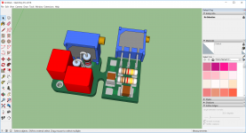
Would it unwise to mount the PCB at the large center bolt used for the typical toroid? Always seems to be some free vertical space there, at least in my builds, and it gets the snubber close to the transformer which is more optimal. And sometimes dual secondary transformers.
BK
JP,
How about something like this post #27.
Nelson Pass' Easy Peasy MOSFET Vgs Measurement
A good pcb would be nice.
How about something like this post #27.
Nelson Pass' Easy Peasy MOSFET Vgs Measurement
A good pcb would be nice.
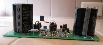
In my opinion, an audio power amplifier with a large transformer (high VA rating) wants very short wires between the secondary and the rectifiers. To keep the secondary wires as short as possible, I think the best place to put CRC snubbers is: piggy-backed above the rectifiers. If the rectifiers are on a PCB then put the snubbers on that board, or air-wired above it. (Example from this thread attached below). You can insulate the leads with electricians tape or paint or heatshrink tubing if it worries you.
If the rectifiers are bolted to the chassis, air-wiring + insulation would seem to be the way to go.
Introducing a new PCB that holds only the snubber(s), seems like it would lengthen the complete go-and-return current pathway, which isn't desrable in my opinion.
_
If the rectifiers are bolted to the chassis, air-wiring + insulation would seem to be the way to go.
Introducing a new PCB that holds only the snubber(s), seems like it would lengthen the complete go-and-return current pathway, which isn't desrable in my opinion.
_
Attachments
Thank you Mark for the information. My GB supply use CRC snubber near rectifiers.
It is possible to replace EPCOS MKT's with ceramic capacitor? I would use SMD components to reduce the size of the CRC retrofit to a minimum (wired, ceramic NPO 10nF/100V; ceramic X7R 150nF/100V, 2x MELF0207 parallel; don't know if 3 pin place holder for multiturn necessary).
JP
It is possible to replace EPCOS MKT's with ceramic capacitor? I would use SMD components to reduce the size of the CRC retrofit to a minimum (wired, ceramic NPO 10nF/100V; ceramic X7R 150nF/100V, 2x MELF0207 parallel; don't know if 3 pin place holder for multiturn necessary).
JP
The great thing about "bell ringer" test jigs with snubbers is, that you can directly observe how well or how poorly this specific individual snubbber actually works. You can install candidate capacitor #1, turn on the bellringer, and dial the Rsnub to find the least objectionable waveform. If you're happy, boom. Done.
If you're not happy, if the least objectionable waveform is still objectionable, then remove capacitor #1 and install candidate capacitor #2 in its place. Turn on the bellringer and dial the Rsnub to find the least objectionable waveform with this new capacitor. Happy? If so, have a pint. If not, proceed on to candidate capacitor #3, and so forth. Install cap, turn on the bellringer, twirl the potentiometer, look at the scope trace, and ask yourself: is this good enough, in my opinion?
If you're not happy, if the least objectionable waveform is still objectionable, then remove capacitor #1 and install candidate capacitor #2 in its place. Turn on the bellringer and dial the Rsnub to find the least objectionable waveform with this new capacitor. Happy? If so, have a pint. If not, proceed on to candidate capacitor #3, and so forth. Install cap, turn on the bellringer, twirl the potentiometer, look at the scope trace, and ask yourself: is this good enough, in my opinion?
Thanks you Mark, DIY´er are never happy!
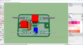
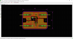
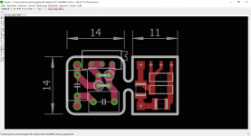
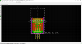
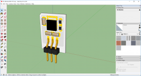
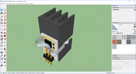
Here´s a version with THT and SMD components (overall dimension 27x14mm):
- THT capacitors pitch 5mm and up to 5mm width; THT resistor radially mounted type 0207; hole for wire
- SMD capacitors up to 1210; SMD resistors MMA or MMB (or 0805, 1206); SMD pad for
JP
Here´s a version with THT and SMD components (overall dimension 27x14mm):
- THT capacitors pitch 5mm and up to 5mm width; THT resistor radially mounted type 0207; hole for wire
- SMD capacitors up to 1210; SMD resistors MMA or MMB (or 0805, 1206); SMD pad for
JP
Attachments
I'd be happy to seeLittle helper from 1st post with softstart for BIG toroid (u know - 20W resistor, shorting relay, delay t RC =0,5 - 1s....
- Status
- Not open for further replies.
- Home
- Group Buys
- Second GB "Little Helpers"