Well after a few days work and searching around I came up with the following circuit. This is the "Zap Filter MK2 clone" test circuit. It has only been used as simulation. I used normal europian transistors. If anybody has any ideas please share.
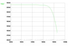
I will post here the schematic and a few graphs.
I will post here the schematic and a few graphs.
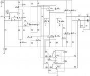
I forgot to say that the you can´t see the input connections like on the original board where you have to make small solderings. I have tried it with voltage input and it works fine.
This version has the bases to a voltage and there is one current input. The negative current input is left in the air with no connection. The input pair is driven as common base, without the 2 DC offset tracking op amps you get a lot of DC at the output.
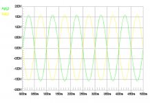
I will post a graphic of the outputs without DC servo circuits. In this case you need capacitors at the outputs.
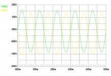
Also you get an unbalance and you have to trim the emitor resistors of Q5 and Q6 to get the 2 signals at the same level. I think this happens because there is only one signal at the inputs.
This version has the bases to a voltage and there is one current input. The negative current input is left in the air with no connection. The input pair is driven as common base, without the 2 DC offset tracking op amps you get a lot of DC at the output.
I will post a graphic of the outputs without DC servo circuits. In this case you need capacitors at the outputs.
Also you get an unbalance and you have to trim the emitor resistors of Q5 and Q6 to get the 2 signals at the same level. I think this happens because there is only one signal at the inputs.
Attachments
Hi,
how did your "reallife" test go? Also did you make a pcb for this? I'm very interested in this because i'm not villing to pay 200EUR for the board and also this would be a "semi" diy projekt. I'm going to build Doedes no DAC and i need balanced out from that, so this would be the perfect thing.
Thx,
Kari
is your circuit working?
i need to build such a circuit and want to know if you got good results?
my thread is here:
http://www.diyaudio.com/forums/showthread.php?s=&postid=1415963#post1415963
Cbriere
i need to build such a circuit and want to know if you got good results?
my thread is here:
http://www.diyaudio.com/forums/showthread.php?s=&postid=1415963#post1415963
Cbriere
Promitheus Hi, I know in your sim you had 1mA feeding the input,
but how much higher than 1mA can you go before one of the stages starts to clip?
Cheers George
but how much higher than 1mA can you go before one of the stages starts to clip?
Cheers George
- Status
- Not open for further replies.
- Home
- Source & Line
- Digital Line Level
- Searching for ZAPfilter Mk2 clone.