Hi,
for a SE amp I need to drive a 27 pF load at around 180 Vpp.
Considering 20 kHz as a target frequency, it is needed 610 uA to drive it.
I would like to use a bootstrapped 12AX7 as a driver mainly because of its mu=100 and good linearity.
Is it acceptable for slew-rate paralleling two 12AX7 at around 2,5-3 mA total? Any better solution?
Thanks in advance,
Roberto
If high gain is required, I would use any small signal pentode with higher plate current (~10 mA).Any better solution?

Thanks @artosalo ,
I need approximately a 100x amplification (I consider 1.6Vpp reasonable as input signal, and 160Vpp are enough for that amp).
Can the pentode be as clean as a triode?
Is a light local positive feedback on linear and low-mu triodes an option?
A pmosfet configured as source follower between cathode and ground, driven by the output of the tube through a voltage divider.
"Can the pentode be as clean as a triode?"
Sample:
10mA CCS loaded D3a, about 198Vpp swing.

IMHO it's enough clean.
BTW which power tube has 27pF input capacitance?
Sample:
10mA CCS loaded D3a, about 198Vpp swing.
IMHO it's enough clean.
BTW which power tube has 27pF input capacitance?
@euro21 Is this plot shown for a triode strapped D3a?
I drive a pmosfet as source follower on the bottom of a pentode in UNSET configuration.
The pmosfet has 27 pF Crss.
@pl802 It's a standard cathode grounded preamp stage.
I would bias the 12AX7 with a green led to ground to have the cathode at around +2V.
I drive a pmosfet as source follower on the bottom of a pentode in UNSET configuration.
The pmosfet has 27 pF Crss.
@pl802 It's a standard cathode grounded preamp stage.
I would bias the 12AX7 with a green led to ground to have the cathode at around +2V.
Last edited:
"I drive a pmosfet as source follower on the bottom of a pentode in UNSET configuration."
Yes that's a grounded grid topology .........what I said.
Okay maybe if you posted a schematic it would help for better understanding
Just as I'm writing u posted!!!
Yes that's a grounded grid topology .........what I said.
Okay maybe if you posted a schematic it would help for better understanding
Just as I'm writing u posted!!!
Nice!
A GU50 Amp.What I use.
Somewhat differently but with fdk too.
Oh btw if you put 12 - 15Vdc on g3 this makes for "sharper knees" .Try it.
Somewhere on here smokingamp posted curves of this.
A GU50 Amp.What I use.
Somewhat differently but with fdk too.
Oh btw if you put 12 - 15Vdc on g3 this makes for "sharper knees" .Try it.
Somewhere on here smokingamp posted curves of this.
Yes, I remember @Wavebourn posted the curves of it on the "better pentode" thread.
Would you connect a rectified and filtered 12Vac winging directly to the cathode of the GU-50?


Would you connect a rectified and filtered 12Vac winging directly to the cathode of the GU-50?
Initially I took it off the GU50 Htr supply but have settled on a dropper resistor off the driver Ht leg.
Both work good....don't ask which I prefer.
Both work good....don't ask which I prefer.
So I have a voltage divider from Ht+ ....with a 15K resistor on the bottom leg for 15Vdc out.
1mA for both channels....hardly anything.Yes g3 is a high impedance input!
Oh and what also helped in deciding this is the data sheet for the PT15 rf pentode shows a side by side of same.......
1mA for both channels....hardly anything.Yes g3 is a high impedance input!
Oh and what also helped in deciding this is the data sheet for the PT15 rf pentode shows a side by side of same.......
Attachments
Thanks @pl802 , so I can also use a zener and a resistor to keep g3 above the cathode by 15V.
@euro21 , thanks for the suggestion of the D3a, but I would like to avoid expensive tubes.
I would prefer to have a circa 5 mA tube with decent mu to drive the GU50, but I am thinking also to use somethink like a ZVN0545A ( https://www.diodes.com/assets/Datasheets/ZVN0545A.pdf ) to buffer the weak 12ax7 and drive the pmosfet.
Instead of increasing the current to drive 27 pF, I can decrease the capacitance to be driven.
By supplying the nmosfet at 200V through GU50's g2 supply, I will also avoid to go beyond the 250V limit of the pmosfet at the bottom of the tube.
What do you think about it?
How is the 27pF figure calculated?
For a driver valve, the triode connected 6EJ7/EF184/6Zh51Pi is tough to beat (mu about 50):
http://www.klausmobile.narod.ru/testerfiles/6j51p.htm
All good fortune,
Chris
For a driver valve, the triode connected 6EJ7/EF184/6Zh51Pi is tough to beat (mu about 50):
http://www.klausmobile.narod.ru/testerfiles/6j51p.htm
All good fortune,
Chris
@Chris Hornbeck
From the datasheet of the FQP9P25 ( https://www.mouser.it/datasheet/2/308/1/FQP9P25_D-1809667.pdf ).
The FQP9P25 reverse transfer capacitance Crss (gate-to-drain capacitance) is 27 pF.
Thanks for the suggestion, I will check if I have the model for it.
From the datasheet of the FQP9P25 ( https://www.mouser.it/datasheet/2/308/1/FQP9P25_D-1809667.pdf ).
The FQP9P25 reverse transfer capacitance Crss (gate-to-drain capacitance) is 27 pF.
Thanks for the suggestion, I will check if I have the model for it.
Looking at the last implementation of @SpreadSpectrum Corona amp ( https://www.diyaudio.com/community/...n-a2-dht-se-amp-prototype.357559/post-7236983 ), with the cathode of the drive directly driven by the OPAMP as buffer
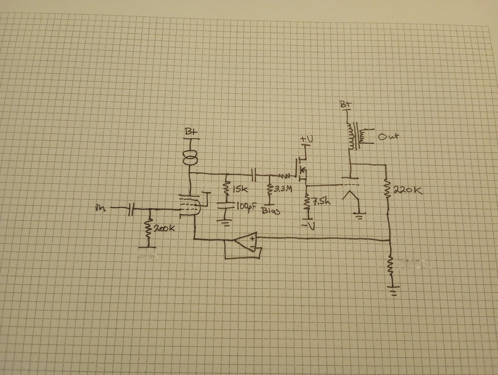
I had another idea on how to apply a feedback circuit I use on my PP amps, based on an OPAMP. The circuit is here below. I have pushed the feedback to the extreme, most probably I will use it way lower.
As a driver there's a 12AT7 with local current feedback through the unbypassed cathode resistor, with the load bootstrapped to become a CCS.
The GU50 has @Tubelab_com reccomandation of 10% local feedback, so only 87 Vpp are needed to drive it to full power.
Then there's the active feedback circuit I'm already using in my EL34 and 6V6GT PP amps:
the trimmer U2 is set so that the amplitude of the output signal from the secondary of the output transformer has the same amplitude of the input signal.
This way at the output of the OPAMP there's only the distortion of the amp, amplified how many times we need/want. The bottom of the resistor at the cathode of the driver is driven through the OPAMP output.
This way I can get the Zout that I want without affecting the sensitivity of the amp. In my PP amps works very very well.
With 95 Ohm on the primary and 0,7 Ohm on the secondary of the output transformer, in simulations I get a Zout of 75 mOhm (DF = 106) with 1 Wrms at 0.03% THD with 120 mVrms at the input, and 17 Wrms at 0.5% THD with 480 mVrms.
Of course I will try it without the global feedback before (the 12AT7 seems to have too much 2nd harmonic), then will apply feedback.
Another advantage of this kind of feedback is that it perfectly removes the PSU hum, so the PSU can be simpler and cheaper.
- Home
- Amplifiers
- Tubes / Valves
- SE driver slew-rate: suggestions welcome