I was reading "Designing Valve amplifiers" By Morgan Jones (Highly Recommended) and saw the page for cancellation using one valve, page 392.
I had some questions.
First, would each winding be 2*RP as a rule of thumb?
Would Av = 2 * mu/mu+1 ~ 1.8?
The circuit looks like it might work great with a toroid and maintain "perfect" balance. It would also work with something like the Lundahl LL1663, but not most classic push pull transformers.
I was thinking I could have a bit different amp.
Any thoughts are appreciated.
I was sketching concepts on my pad for this and thought I'd throw it out for comments.
Doug
Last edited:
I was reading "Designing Valve amplifiers" By Morgan Jones (Highly Recommended) and saw the page for cancellation using one valve, page 392.
I had some questions.
First, would each winding be 2*RP as a rule of thumb?
Would Av = 2 * mu/mu+1 ~ 1.8?
The circuit looks like it might work great with a toroid and maintain "perfect" balance. It would also work with something like the Lundahl LL1663, but not most classic push pull transformers.
I was thinking I could have a bit different amp.
Any thoughts are appreciated.
I was sketching concepts on my pad for this and thought I'd throw it out for comments.
Doug
I think it could work well with triodes like the 6080/6AS7 that have a very low mu anyway....
Cheers,
45
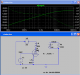
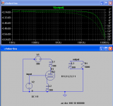
It seems like such a nice concept. However, the problem is that the AC signals will exactly cancel each other out leaving you with almost exactly no output. That is, it is an error in the book.
Sims are from Slagle from a while back. Also, if you search AA for "chokertina" there was a discussion on this in 2003.
Sims are from Slagle from a while back. Also, if you search AA for "chokertina" there was a discussion on this in 2003.
Attachments
I was thinking about something like the Klimo Beltaine. Using the 6AS7, one triode is the amplier and the other for the DC balance only. Cathode follower config. if you like. Probably it doesn't work as well because the DC side has to be a current source.
I don't have the book by Morgan Jones .
Cheers,
45
I don't have the book by Morgan Jones .
Cheers,
45
Last edited:
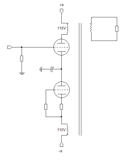
Here is The Concept.
Push pull transformer with split, not center tap primary.
Standing current cancels. And since there is only 1 tube and Icathode and IPlate are equal until A2, the current ballance should be "perfect".
Morgan Jones said it was a problem to drive.
Doug
Push pull transformer with split, not center tap primary.
Standing current cancels. And since there is only 1 tube and Icathode and IPlate are equal until A2, the current ballance should be "perfect".
Morgan Jones said it was a problem to drive.
Doug
Attachments
It seems like such a nice concept. However, the problem is that the AC signals will exactly cancel each other out leaving you with almost exactly no output. That is, it is an error in the book.
Sims are from Slagle from a while back. Also, if you search AA for "chokertina" there was a discussion on this in 2003.
Really?
Thanks.
Sounded too good to be true.
Doug
"The ac signals at the anode and cathode are opposite phase right?"
Yes, but they are then connected to the same phase connections on the xfmr where they then cancel out.
Some related ideas here:
http://www.diyaudio.com/forums/tubes-valves/52175-dc-compensated-se-output-transformer.html
Yes, but they are then connected to the same phase connections on the xfmr where they then cancel out.
Some related ideas here:
http://www.diyaudio.com/forums/tubes-valves/52175-dc-compensated-se-output-transformer.html
Hello revintage,
Finally you abandoned the concept with two tubes? 😉
- Elias
Finally you abandoned the concept with two tubes? 😉
- Elias
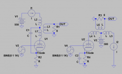
Two realistic ways of doing it:
Hey Elias,
Absolutely not🙂! But the twotube amps are covered elsewhere at this forum and already playing.
The left one above is still on my bench to be readybuilt with only some soldering left and as far as I remember it was you who presented the old patent (all iron) that inspired me. Have given it more thought and will probably use a pentode(D3a or E280F) for driver and a Schaded tetrode(6L6) for output with gyrator instead of CCS on top. Have simmed it and it looks great so far.
The right one could actually be using a pentode CCS and thus be twotube😀.
What about your current-compensation project? Never heard if you ended up with a complete working amp.
There are not so many solutions to remove DC magnetisation, just one:
Have a DC current in opposite direction in ANY winding of the transformer giving the same number of "ampère * turn" and apply it thru an hi impedance circuit so that it does not short the AC voltage.
That is a CCS.
No matter wich kinda . . . tube, sand, inductor or . . . what else ?
Yves.
<edit>
Someone tried permanent magnet ?
</edit>
Except for the weight and the size of the transformer, I cannot see the evil in a normal SE OPT. It is true that many ready available OPT's are made for generic applications and often they are not the optimal choice.
However a well designed SE OPT will just work fine (contributing very little to THD at least down to 30-40 Hz, depending on the design). Usually the power handling of OPT's is very optimistic. When you find the power handling without the frequency that means that is assumed to be 50-60 Hz!!
Using the right core, the right number of turns and the right gap the transformer will just work fine. Typically the dominant harmonic of the transformer distortion (when approaching the saturation) is the 3rd, so there is no chance to cancel it out even in a PP amp.
A small gap is desirable even in PP OPT's in order to avoid this problem, regardless if you have a DC-compensated SE or a normal PP output stage.
In fact if you use half of the winding with a CCS to compensate the DC magnetization you have no guarantee that the compensation will stand in any modulation condition because the tube does not draw a constant current when approaching the max output. You must force the power tube to draw constant current which doesn't sound good to me.
From my point of view a 845 SE with a small OPT would look poor!
It must be huge in any sense....😀😀
Cheers,
45
Last edited:
Also you have practically no chance to find an OPT where the power handling is specified for a precise frequency and a precise THD.
This is just the case of high quality signal and interstage transformers.....
This is just the case of high quality signal and interstage transformers.....
Hello,
I think this idea WILL work with slight modifications/additions 🙂
Yesterday I hit my head with the cupboard door and got this idea:
However, it uses two valves 😀 But the benefits of using PP transformer or mains toroid are there!
- Elias
I was reading "Designing Valve amplifiers" By Morgan Jones (Highly Recommended) and saw the page for cancellation using one valve, page 392.
I think this idea WILL work with slight modifications/additions 🙂
Yesterday I hit my head with the cupboard door and got this idea:
However, it uses two valves 😀 But the benefits of using PP transformer or mains toroid are there!
- Elias
Hello,
So you are seriously targeting for a hybrid amp with transistors then? 😉
Which one you prefer of the two from your pic?
Well, my current compensated toroid projekt ended up with a very well functioning proto on the table 😀 One day it will be a complete amp! However, in the spirit of continous research and development at the moment I'm using a chip amp 😱 😀
😱 😀
- Elias
...Have given it more thought and will probably use a pentode(D3a or E280F) for driver and a Schaded tetrode(6L6) for output with gyrator instead of CCS on top. Have simmed it and it looks great so far.
The right one could actually be using a pentode CCS and thus be twotube😀.
What about your current-compensation project? Never heard if you ended up with a complete working amp.
So you are seriously targeting for a hybrid amp with transistors then? 😉
Which one you prefer of the two from your pic?
Well, my current compensated toroid projekt ended up with a very well functioning proto on the table 😀 One day it will be a complete amp! However, in the spirit of continous research and development at the moment I'm using a chip amp
😱 😀- Elias
- Status
- Not open for further replies.
- Home
- Amplifiers
- Tubes / Valves
- Se Amp with Push Pull Transformer