From a Chiro Kinergetics Research amp like
http://www.diyaudio.com/forums/soli...ics-research-c-300-c300-schematic-wanted.html
I have created the schematic. I note, there was embedded a screened cable in the feedback loop.
But not in the kind as to find about
http://www.diyaudio.com/forums/solid-state/181918-cable-part-feedback-loop.html
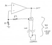
Instead this was the cable connected as follow:
- One end of the 40 cm long cable was created a connection (short wire) between the hot wire and screen.
- From the other end goes the screen to the NFB resistor and the hot wire to the NFB Input (inverted input of the differential input amp).
- Additional the screened cable is wound in the kind of follow picture:
http://estreo.com/foto/l-Klassische...tenVerwendetdieTipExchangeTechnologieFXL1.jpg
I have this never see before and I don't find any advicves in audio amplifier basic books concerning the target for this.
Who knows more about pros and cons concerning this?
Thanks for your advices.
http://www.diyaudio.com/forums/soli...ics-research-c-300-c300-schematic-wanted.html
I have created the schematic. I note, there was embedded a screened cable in the feedback loop.
But not in the kind as to find about
http://www.diyaudio.com/forums/solid-state/181918-cable-part-feedback-loop.html
Instead this was the cable connected as follow:
- One end of the 40 cm long cable was created a connection (short wire) between the hot wire and screen.
- From the other end goes the screen to the NFB resistor and the hot wire to the NFB Input (inverted input of the differential input amp).
- Additional the screened cable is wound in the kind of follow picture:
http://estreo.com/foto/l-Klassische...tenVerwendetdieTipExchangeTechnologieFXL1.jpg
I have this never see before and I don't find any advicves in audio amplifier basic books concerning the target for this.
Who knows more about pros and cons concerning this?
Thanks for your advices.
Last edited:
Screened cable for neg feedback loop ... why?
There is no plausible reason to do this.
If one wished to be pedantic, screened lead has a capacitance and the feed back will stop at HF which of course is not desired.
There is no plausible reason to do this.
If one wished to be pedantic, screened lead has a capacitance and the feed back will stop at HF which of course is not desired.
If I understand you correctly, the shorted cable was used as a connection between the feedback resistor and the feedback input. This provides a connection for audio signals. In addition, it will:Instead this was the cable connected as follow:
- One end of the 40 cm long cable was created a connection (short wire) between the hot wire and screen.
- From the other end goes the screen to the NFB resistor and the hot wire to the NFB Input (inverted input of the differential input amp).
- add a very small inductance to the feedback resistor (a shorted coax looks like an inductor at low frequencies) - which will probably do little harm
- add a short antenna to the feedback point - even coiled up it will still pick up some RF
- do strange things at VHF frequencies, but fortunately the amp is unlikely to have any gain up there so little harm will be done
I am sure the 'designer' will have a 'good story' to tell. It will almost certainly be complete bunkum, which he may or may not realise himself. If there is any audio effect it will come from the RF pickup adding spurious 'air' (i.e. down-modulated interference) around instruments!
I suggested a few years back to another Member that he look at adding a guard ring around the very long feedback wire to the feedback resistor located at the amps -IN pin.
The coax with both core and screen connected to the very low impedance output node would achieve both the feedback via the core and the guard ring via the screen connected at the output only.
The coax with both core and screen connected to the very low impedance output node would achieve both the feedback via the core and the guard ring via the screen connected at the output only.
That might have some merit, but I don't think that is what the OP is describing. He describes the coax as being shorted at one end, and connected to the circuit at the other end.AndrewT said:The coax with both core and screen connected to the very low impedance output node would achieve both the feedback via the core and the guard ring via the screen connected at the output only.
Convenience, often.
In my tweeter amp I do this in order to return both the "common" end of the output and the "hot" end of the output to the feedback points in the first stage, but I suspect that there's only a minuscule performance advantage to doing so. That doesn't seem to be the case here, but we can always fall back on the "convenience" excuse.
In my tweeter amp I do this in order to return both the "common" end of the output and the "hot" end of the output to the feedback points in the first stage, but I suspect that there's only a minuscule performance advantage to doing so. That doesn't seem to be the case here, but we can always fall back on the "convenience" excuse.
Could we have a diagram to confirm exactly which circuit we are considering? There are 12 ways to connect a symmetric coax into 4 circuit nodes. Some of them don't make much sense, but that doesn't mean someone is not using them!
I can't recall for sure but I think I've seen somewhere on ESP the use of shielded cable for the feedback path between the output / inverting input. The reason given was to protect longer feedback paths from interference as it's a higher impedance node (in VFAs, generally).
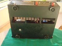
Thank you very much for this interesting advices. On the third picture you will see the white coax wire in left of the second blue electrolytic cap.There's a chance they are considering the coax to be a non-linear element whose distortion needs to be cancelled, and then attempting to cancel it using circuitry from The Kinergetics Patent (link)
Attachments
-
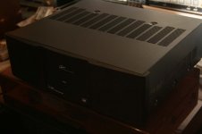 Chiro Kinergetics C-200 front-top.jpg53.9 KB · Views: 212
 -
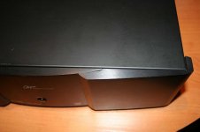 Chiro Kinergetics C-200 front+top.jpg59.7 KB · Views: 211
 -
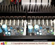 Chiro Kinergetics C-200 PCB top view.jpg119.2 KB · Views: 226
 -
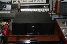 Chiro Kinergetics C-200 front view.jpg78.8 KB · Views: 214
 -
 Chiro Kinergetics C-200 bottom view.jpg27.3 KB · Views: 199
Last edited:
A bit of carefully and sparingly sprinkled snake oil can do no harm technically speaking, but it can do wonders from a marketing perspective.Thank you very much for this interesting advices. On the third picture you will see the white coax wire in left of the second blue electrolytic cap.
One is born every minute; that was true when it was first proffered, but nowadays with the world's population close to 8 billion, it is closer to one every second: a huge reservoir of potential "customers"
BTW, inserting pure delay in a feedback system is about the worst thing you can do for stability
the cable connected as follow:
- One end of the 40 cm long cable was created a connection (short wire) between the hot wire and screen.
- From the other end goes the screen to the NFB resistor and the hot wire to the NFB Input (inverted input of the differential input amp).
Like this?
Above 750 kHz or so, the phase shift contributed by that roundtrip delay, begins to exceed ten degrees. Yikes.
Attachments
Yes. The only different is the direction of connection. Screen is connected to the output and the hot wire with R2. But this doesn't matter, so I think.Like this?
Above 750 kHz or so, the phase shift contributed by that roundtrip delay, begins to exceed ten degrees. Yikes.
- Status
- Not open for further replies.
- Home
- Amplifiers
- Solid State
- Screened Coax Cable in the Feedback Loop - which Purpose and Benefit is there ??