Hi-
I'm just finishing up another small 'practice amp' (ADA Rocket 10) .
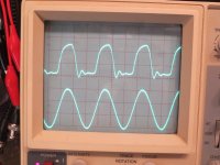
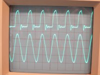
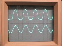
Wide open, I get more overdriven/distorted sound than I expected. The scope trace shows distortion on the output that's not present at the grid of the EL84 power tube.
Please have a look at the attached picture of the scope traces - input is 1000Hz sine wave - bottom trace is the input at the EL84 grid pin, output is across 8 ohm dummy load (or speaker)- Display volts/div adjusted to make traces the same size.
The EL84 is cathode biased (with bypass cap) and running at about 9 watts (30mA @ 300 volts or so).
Output transformer is a cheap one I salvaged from an old tube (6BQ5) stereo console.
Comments? Solutions?
Can too much voltage swing at the input grid cause this output problem?
I'm just finishing up another small 'practice amp' (ADA Rocket 10) .
Wide open, I get more overdriven/distorted sound than I expected. The scope trace shows distortion on the output that's not present at the grid of the EL84 power tube.
Please have a look at the attached picture of the scope traces - input is 1000Hz sine wave - bottom trace is the input at the EL84 grid pin, output is across 8 ohm dummy load (or speaker)- Display volts/div adjusted to make traces the same size.
The EL84 is cathode biased (with bypass cap) and running at about 9 watts (30mA @ 300 volts or so).
Output transformer is a cheap one I salvaged from an old tube (6BQ5) stereo console.
Comments? Solutions?
Can too much voltage swing at the input grid cause this output problem?
Attachments
DJ-
Thanks for the reply.
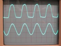
It's biased with a cathode resistor, so the bias voltage changes with the input signal. (I understand this is normal...)
Here's some data:
Grid Voltage p-p Bias Voltage DC v Current (mA)
0 .......................12.5 ...................22
10......................13.1....................23
20......................14.9....................26
30......................17.1....................30
36......................19.0....................34
Pics attached - bottom trace is input at EL84 grid
Thanks for the reply.
It's biased with a cathode resistor, so the bias voltage changes with the input signal. (I understand this is normal...)
Here's some data:
Grid Voltage p-p Bias Voltage DC v Current (mA)
0 .......................12.5 ...................22
10......................13.1....................23
20......................14.9....................26
30......................17.1....................30
36......................19.0....................34
Pics attached - bottom trace is input at EL84 grid
Attachments
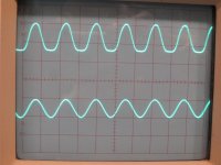
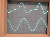
I'm wondering if the output transformer has something to do with it. Was the salvaged transformer from a single-ended amp? What happens at lower frequencies (e.g. 100Hz)?
I'm wondering if the output transformer has something to do with it. Was the salvaged transformer from a single-ended amp? What happens at lower frequencies (e.g. 100Hz)?
Yes, the salvage OT was from a SE stereo console amp.
I'm thinking it may be an OT-related thing since the wobbles (ringing?) in the waveform are not so obvious at lower frequencies.
Aside from the 'ringing', I do wonder why it is clipping only one 'side' of the wave...or is this common?
I swapped in a known good (and much better quality) OT10SE transformer from musicalpowersupplies and the ringing problem then appeared at higher frequencies (>3k vs >1kHz) than with the salvage OT. Clipping was the same pattern.
Last edited:
Looks to me like bias on el84 is wrong and the signal is clipping more on one half phase than the other.
Looks to me like bias on el84 is wrong and the signal is clipping more on one half phase than the other.
Nigel-
That's what I was thinking, but if the grid is swinging 10 volts on either side of a 15volt bias, what could be the problem, exactly?
If it was swinging more than the bias and getting into grid conduction it would make more sense to me. My understanding is not very sophisticated, I know.
Hi, Without seeing a schematic I can not be sure, but it is likely the output impedance is incorrect. You said you didn't know what the transformer impedance was....can you tell us more about the source. Another possibility is that the bias via the cathode resistor is not optimal. What is the value of the resistor? Glad to assist, just need more information.
Did I say that?🙂Hi, Without seeing a schematic I can not be sure, but it is likely the output impedance is incorrect. You said you didn't know what the transformer impedance was....
The salvage OT has a 5.7k primary:8 ohm secondary and came from a SE 6BQ5 (aka EL84) console tube amplifier.
HAnother possibility is that the bias via the cathode resistor is not optimal. What is the value of the resistor? Glad to assist, just need more information.
I may have the tube biased too cold (??). That's one of the things I'm going to try next. The operating conditions are in one of the posts above with the bias voltage, and current listed. The B+ is about 310 v, so plate to cathode is about 295v. Dissipation is around 9 watts @ 30mA by my 'back of envelope' calculations.
Present bias resistor is 560 ohm.
Schematic called for less, but I couldn't make the schematic numbers work so upped the bias resistor value.
Here's a schematic:
Attachments
Quick update:
1) A lower bias level doesn't affect the scope waveform at all. I put a 500 ohm pot/variable resistor in parallel with the bias resistor to test this quickly. I'll probably bias the tube a bit hotter anyway, more in line with some ideas I've read online.
2) I re-attached the original (salvage) OT since the better OT didn't make a huge difference.
3) What did make a difference was connecting a speaker instead of dummy load. Output waveform was a lot more symmetrical and 'normal' looking...something I should have thought of sooner, not that it would have been welcome to do 1-5 kHz testing here last evening at midnight with a speaker!
I'm still curious about this whole situation, though, so I'd be happy to continue the discussion with further tests, etc.. I'd like to get this 'cleared up' as much as possible before proceeding with a VVR which I have planned for this amp.
Did you include the enable/disable switch for the negative feed back? (Labelled 'Power Amp Thrust' on the schematic!) If so, how does that affect the waveform?
Did you include the enable/disable switch for the negative feed back? (Labelled 'Power Amp Thrust' on the schematic!) If so, how does that affect the waveform?
The NFB switch (I used the variant from the RA20) affects the amplitude of the output wave but not its shape...which didn't surprise me, since the NFB signal is the same as the output, so 'subtracts evenly' from the output.
The whole situation with the output being quite different with a speaker vs dummy load is a good lesson, I suppose. I sometimes forget how 'uneven' the speakers are in their impedance etc..
I was curious if the wire-wound resistor I was using for a dummy load was behaving differently from a ceramic (sand) resistor, but there was no difference when tested - the 'ringing' and uneven clipping on the output was still there.
I have a similar amp - Peavey Roal 8 - which has been a platform for much experimentation.
I used a pot in the bias to maximise clean out into a resistive load - and got a whopping 1watt for a B+ of 280v.
My reading on this and other forums like sewatt and ax84 indicates that el84's stop sounding good beyond a certain level of grid signal.
There is a range of options to achieve this.
In the PA; use a zener in the cathode to stop bias moving above a spec voltage, or a zener (or two) on the grid to limit the signal peaks (search for ruby mod); or more simply, add a MV pot between preamp and power tube.
In the preamp there are a lot of options to limit the signal appearing on the el84 grid.
I have had a lot of fun experimenting with this amp and I am very happy with its sound, even with its original cheap trafo.
(And for "more " it has an EF95 in front of the 12AX7)
Cheers
JimG
Last edited:
Your Rocket schematic doesn't show a screen stopper on the output tube.
That's a no brainer to fix - minimum of 1k and anything up to big for experimental fun.
That's a no brainer to fix - minimum of 1k and anything up to big for experimental fun.
Look at the grid of the EL84 with the scope DC coupled. I think grid conduction is pushing the input more negative (the mid point of the sine goes negative) as grid current charges up the coupling cap from the previous stage. The flat part of the output wave is when the tube is cutoff, the rounded part with when the input tries to go positive (relative to the cathode) but grid conduction prevents the top of the wave from making a nice flat top. You need a large grid stopper, perhaps 22K.
Thanks for those suggestions.
I do have some info on the 'Ruby mod' (and the Ivers mod) using zeners and will look at that again.
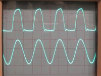
I had added a 10k grid stopper on the EL84 after some research online which also suggested a cap to (ground or) the bypassed cathode as useful in SE cathode biased stages. I added a .001uF cap when I put the grid stopper in there. Neither the cap nor stopper helped with the ringing/clipping problem.
I added a 10k screen stopper just now - no effect on scope trace.
Flipping the scope input switch on the grid voltage channel to DC from AC had no effect. I don't know if that was the recommendation....
A couple of days ago I also tried a conjunctive filter (parallel .06uF & 10k resistor) across the OT primary to no effect.
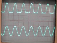
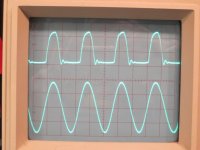
Here's the scope image- before and after the changes above.
3kHz sine input
Output to dummy load
Grid voltage (wide-open) 36v p-p
Cathode bias 14.5v
I do have some info on the 'Ruby mod' (and the Ivers mod) using zeners and will look at that again.
I had added a 10k grid stopper on the EL84 after some research online which also suggested a cap to (ground or) the bypassed cathode as useful in SE cathode biased stages. I added a .001uF cap when I put the grid stopper in there. Neither the cap nor stopper helped with the ringing/clipping problem.
I added a 10k screen stopper just now - no effect on scope trace.
Flipping the scope input switch on the grid voltage channel to DC from AC had no effect. I don't know if that was the recommendation....
A couple of days ago I also tried a conjunctive filter (parallel .06uF & 10k resistor) across the OT primary to no effect.
Here's the scope image- before and after the changes above.
3kHz sine input
Output to dummy load
Grid voltage (wide-open) 36v p-p
Cathode bias 14.5v
Attachments
As a side note, what output problem? Looks fine to me.
1) if you feed enough signal to the power tube, it will eventually clip.
2) being single ended and overdriven, asymmetrical waveform is the norm, and symmetrical the exception.
3) that said, impedance does not look properly matched.
*ONE* possible idle current setting + output impedance combination calls for plate clipping at the exact same point that grid starts clipping (because it starts getting positive) but it's neither the only possibility nor necessarily the "best" . (it's a guitar amp).
I would retest but doubling and halving load impedance, one will be "better" (at least more symmetrical and you might clip power tube grid) , the other will be the opposite.
Try all 3 and post results.
Last edited:
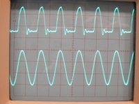
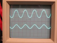
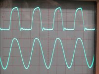
Look at the grid of the EL84 with the scope DC coupled. I think grid conduction is pushing the input more negative (the mid point of the sine goes negative) as grid current charges up the coupling cap from the previous stage. The flat part of the output wave is when the tube is cutoff, the rounded part with when the input tries to go positive (relative to the cathode) but grid conduction prevents the top of the wave from making a nice flat top. You need a large grid stopper, perhaps 22K.
I think I understand a bit better now - I looked more closely at the (DC-coupled) grid voltage on the scope. As the drive level is increased, at some point the grid sine wave stops 'growing' on the top/positive end and all the increase is on the 'bottom'/negative-going part of the wave.
Is this what you meant?
Here's a series of pics with increasing drive - scope controls untouched.
I'll try increasing that grid stopper from the present 10k and see if it has an effect on this.
Attachments
- Status
- Not open for further replies.
- Home
- Live Sound
- Instruments and Amps
- Scope distortion pattern- diagnose problem?