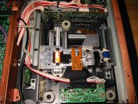
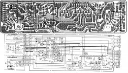
Who can help me - I need schematic diagram of the rf PCB of BU1C (BU = Base Unit = CD transport mechanism include RF and Servo PCB's)
For this base units Sony must have service manuals - similare like Philips by the CDM1, 2 and CDM3
It should not be confused with the BU-1E, which is identical except the RF PCB and the RF circuit (CXA1081 instead CX20109). Also not with the type "BU-1".
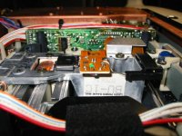
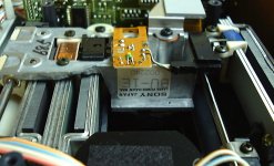
By the way - the Laser Unit (optical pick up) is without type No by all BU1 variations.
I need especially the APC circuit include the P-SUB or N-SUB laser diode. The variable resistor (pot) of APC circuit is integrated on the RF PCB and not - as commonly to observe - on the optical pick up (laser head).
Follow BU1 variantes are inside by follow models:
BU-1 = BU1: CDP102 - CDP302 - CDP502ES - CDP520ES - CDP552ESD - CDP620 - CDP650 (CDP-102 - CDP-302 - CDP-502ES - CDP-520ES - CDP-552ESD - CDP-620 - CDP-650 CDP-502 ES - CDP-520 ES - CDP-552 ESD CDP502 ES - CDP520 ES - CDP552 ESD)
BU-1C = (X49082061) = BU1C: CDP303ES - CDP303ESII - CDP502ESII - CDP552ESDII - CDP553ESD - CDP620ESII - CDP650ESDII (CDP-303ES - CDP-303ESII - CDP-502ESII - CDP-552ESDII - CDP-553ESD - CDP-620ESII - CDP-650ESDII CDP-303 ES - CDP-303 ES-II - CDP-502 ES-II - CDP-552 ESD-II - CDP-553 ESD - CDP-620 ES-II - CDP-650 ESD-II) ACCUPHASE DP-70, DP-80, DP70, DP80
BU-1E = (X49150331) = BU1E: CDP333ESD - CDP555ESD - CDP605ESD - CDP705ESD (CDP-333ESD - CDP-555ESD - CDP-605ESD - CDP-705ESD - CDP333 ESD - CDP555 ESD - CDP605 ESD - CDP705 ESD - CDP-333 ESD - CDP-555 ESD - CDP-605 ESD - CDP-705 ESD) and Onkyo Grand Integra DX-G10
more details you will find there:
BU-1C:
ƒ\ƒj�[�@‚b‚cƒvƒŒ�[ƒ„�[�@‚b‚c‚o�|‚T‚T‚R‚d‚r‚cŒ^�i‚»‚Ì‚P�j
BU-1E:
CDP-555ESD‚̃XƒyƒbƒN‚Æ“à•”ŽÊ�^
1986Äê³ö²úµÄͬÆÚ²úÆ· CDP-555ESD 333ESD ... - ¾°´óÇìµÄÈÕÖ¾ - ÌÔ½*ºþ - ÌÔ±¦Íø
and by the attached photos:
For this base units Sony must have service manuals - similare like Philips by the CDM1, 2 and CDM3
It should not be confused with the BU-1E, which is identical except the RF PCB and the RF circuit (CXA1081 instead CX20109). Also not with the type "BU-1".
By the way - the Laser Unit (optical pick up) is without type No by all BU1 variations.
I need especially the APC circuit include the P-SUB or N-SUB laser diode. The variable resistor (pot) of APC circuit is integrated on the RF PCB and not - as commonly to observe - on the optical pick up (laser head).
Follow BU1 variantes are inside by follow models:
BU-1 = BU1: CDP102 - CDP302 - CDP502ES - CDP520ES - CDP552ESD - CDP620 - CDP650 (CDP-102 - CDP-302 - CDP-502ES - CDP-520ES - CDP-552ESD - CDP-620 - CDP-650 CDP-502 ES - CDP-520 ES - CDP-552 ESD CDP502 ES - CDP520 ES - CDP552 ESD)
BU-1C = (X49082061) = BU1C: CDP303ES - CDP303ESII - CDP502ESII - CDP552ESDII - CDP553ESD - CDP620ESII - CDP650ESDII (CDP-303ES - CDP-303ESII - CDP-502ESII - CDP-552ESDII - CDP-553ESD - CDP-620ESII - CDP-650ESDII CDP-303 ES - CDP-303 ES-II - CDP-502 ES-II - CDP-552 ESD-II - CDP-553 ESD - CDP-620 ES-II - CDP-650 ESD-II) ACCUPHASE DP-70, DP-80, DP70, DP80
BU-1E = (X49150331) = BU1E: CDP333ESD - CDP555ESD - CDP605ESD - CDP705ESD (CDP-333ESD - CDP-555ESD - CDP-605ESD - CDP-705ESD - CDP333 ESD - CDP555 ESD - CDP605 ESD - CDP705 ESD - CDP-333 ESD - CDP-555 ESD - CDP-605 ESD - CDP-705 ESD) and Onkyo Grand Integra DX-G10
more details you will find there:
BU-1C:
ƒ\ƒj�[�@‚b‚cƒvƒŒ�[ƒ„�[�@‚b‚c‚o�|‚T‚T‚R‚d‚r‚cŒ^�i‚»‚Ì‚P�j
BU-1E:
CDP-555ESD‚̃XƒyƒbƒN‚Æ“à•”ŽÊ�^
1986Äê³ö²úµÄͬÆÚ²úÆ· CDP-555ESD 333ESD ... - ¾°´óÇìµÄÈÕÖ¾ - ÌÔ½*ºþ - ÌÔ±¦Íø
and by the attached photos:
Attachments
Last edited:
Can I use the CXA1081 with KSS-123A?
On CXA1081, is Pin Nr. 4 a selector for p-sub/n-sub diodes?
(Low: p-sub High: n-sub)
Or has a n-sub diode to be attached to pin 4?
What about APC and current/voltages?
I want to try a (n-sub I guess) KSS-123A with a board with the CXA1081. The board is orignally intended for a KSS-213C. I read 0.6V for the kss-213C laser diode, I assume, voltage for the KSS-123a needs to be higher?
All the best, Sal
Last edited:
You need actually the data sheets both of CXA 1081 and KSS123A
from the CXA1081 you can use the data sheet of Samsung's KA9201 (direct replacement):
KA9201 datasheet pdf datenblatt - Samsung semiconductor - RF AMP FOR CDP ::: ALLDATASHEET :::
the data sheet of KSS-123A isn't to find online. Observe this thread in this case:
http://www.diyaudio.com/forums/digi...k-about-sonys-kss-optical-pick-up-series.html
as long no data sheet isn't to find, you can only try to find out the cd player models uses both at the same time and then you can order the associated service manual.
Hallo Tiefbassubertragung,
vielen Dank for the link.
The aim is, to run a KSS-123A with a circuitry that was oruginally designed
for the KSS-213C (and probably suitable for many which werde brought ot after the KSS-123A).
One question about the APC:
Should the apc not be linear anyway? So that a designer could use almost any CD-laser-type, as long as it is based on P-sub/n-sub + 6 photodiode array?
All the best,
Sal
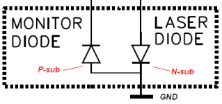
I don't know, what means exactly "P-Sub" and "N-Sub" Laser diodes consists in general of two diodes (except any modern high power light diodes for burner):Hallo Tiefbassubertragung,
vielen Dank for the link.
The aim is, to run a KSS-123A with a circuitry that was oruginally designed
for the KSS-213C (and probably suitable for many which werde brought ot after the KSS-123A).
One question about the APC:
Should the apc not be linear anyway? So that a designer could use almost any CD-laser-type, as long as it is based on P-sub/n-sub + 6 photodiode array?
All the best,
Sal
1) the Monitor Diode (also called Photo Diode or PD resp MD)
2) the actually laser diode (LD)
there naturally three legs (3 pin's)
One of the pins is the substrat leg on the enclosure of the cabinet housing from this diode.
follow pin-out is possible:
1) both kathodes on the substrat
2) both Anodes on the substrat
3) K,PD and A,LD on the substrat
4) A,PD and K,LD on the substrat
the terms P-Sub or N-SUB is refer to the LD or MD (PD) - that I don't know.
The detection reference of the APC-Circuit is - as I know - the light value and not the electrical current flow of the laser diode
As far as I understand the KA9201 datasheet , p-sub / n-sub refers always to the laser diode.
And I guess, the detection reference of the APC-Circuit is the electrical current flow from the monitor diode, triggerd by the lasser´s diode light emission...?
And I guess, the detection reference of the APC-Circuit is the electrical current flow from the monitor diode, triggerd by the lasser´s diode light emission...?
Thanks!
looking at serveral cd-player´s circuits, the laser diode can be p-sub or n-sub, while the monitor diode stays p-sub...
Anyway, I wll try a KSS123A in a circuitry which is intended for a KSS-213C.When I am lucky, only pin 4 at CX1081 has to be put to "high".
Still, any information if the CX1081 APC circuitry is versatile to drive different types of laser diodes would be helpful...
Last edited:
Thanks!
looking at serveral cd-player´s circuits, the laser diode can be p-sub or n-sub, while the monitor diode stays p-sub...
Anyway, I wll try a KSS123A in a circuitry which is intended for a KSS-213C.When I am lucky, only pin 4 at CX1081 has to be put to "high".
Still, any information if the CX1081 APC circuitry is versatile to drive different types of laser diodes would be helpful...
What information you need, which isn't mentioned about the datasheet link about post #3?
What information you need, which isn't mentioned about the datasheet link about post #3?
There is a very good book available from Ken Clements:
"Understanding and Servicing CD-Players"
first published 1994 by Newnes
There, he also explains integrated circuits like the CXA1081S.
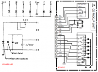
Quote from page 74:
"Laser power control
When LDON signal from the system control applied to pin 29 is LOW, the output at pin 5will also go LOW, allowing transistor Q1 to conduct, switching on the laser diode.
The monitor diode MD passes to pin 6 a measurement of the light intensity from the laser diode which enables the automatic power control circuit (APC)
formed by the two internal opamps to maintain a stabilised laser diode output.
VR1 (i.e the variable resistor on the laser head) provides the the operating point for the circuit via pin 6 to determine the necessary laser intensity from the laser diode."
Questions are:
Because the CXA1081S/KA9201 were used in many player with so many differnt types of laser heads (I assume), the APC is versatile, and any laser can be used with it without any modifications to the circuit?
OR:
Does the following transistor has to mach the laser diodes - data which we cannot find.
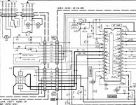
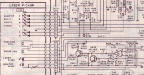
I attached 2 APC circuits, the one with a red tint is with a KSS-123A (Nakamichi OMS-5II).
The other one is with KSS-213 attached to CXA1081S. (Kenwood DP1020)
I would like to attach the KSS-123A to the CX1081 of the Kenwood´s circuit.
Choosing p-sub/n-sub must be easy. But will the KSS-123A get the exact laser current needed?
Attachments
Last edited:
Ooops, I made a big mistake.
The laser in the CXA1081 circuitry is NOT a KSS213A.
It is KSS-150A
So this is about running a KSS-123A in a KSS-150A circuitry,
with CXA1081S RF-amp and APC.
Hm, KSS123A and KSS150A, they are almost the same generation..?
The laser in the CXA1081 circuitry is NOT a KSS213A.
It is KSS-150A
So this is about running a KSS-123A in a KSS-150A circuitry,
with CXA1081S RF-amp and APC.
Hm, KSS123A and KSS150A, they are almost the same generation..?
KSS-120C and KSS-150A share the same diode, SLD104AU, right?
In SLD104AU, the laser diode and monitor diode share a common cathode.
In the KSS-123A, developed the same time as the KSS-120, the photo diodes cathode is connected to the laser diodes anode.
But maybe electrical characteristics of KSS-123A and KSS-120/150 are still the same...?
To artegatgt:
Sorry I put you on the wrong track with wrong kss-213. But circuit differences are still the same, also in the KSS-150, laser diode and monitor diode share a common cathode..
This is why CXA1081 has a pin to choose between p-sub and n-sub. The arrangement of the Monitor/laser diode in KSS-123A is exactly like you described in your post
Last edited:
the obviously different between KSS-123A and KSS-120/150/152 seems to be only the contrary polarity laser diode. The optical block, foto diode matrix, focus coil, tracking coil, accutator and lens seems to be the same.
All CD player I know using KSS-123A haven't integrated ACP circuit on the RF chip like CXA1081 - instead this solution I see still a discrete outdoor APC solution.
All CD player I know using KSS-123A haven't integrated ACP circuit on the RF chip like CXA1081 - instead this solution I see still a discrete outdoor APC solution.
Last edited:
- Status
- Not open for further replies.
- Home
- Source & Line
- Digital Source
- Schematic wanted for SONY's CDP-553ESD RF Amp inside in BU-1C