Hi All
Anyone know where I can get the schematic for the Pro-ject phono box?
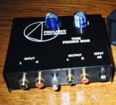
http://e-dizain.de/project/en/phonobox.html
Thanks for any inf
Smiffy
Anyone know where I can get the schematic for the Pro-ject phono box?
http://e-dizain.de/project/en/phonobox.html
Thanks for any inf
Smiffy
dimitri said:That pretty stupid thing is here:
What makes it stupid? (just curious)
Dimitri was kind enough to send me some measurements of the unit showing it to be somewhat out with regards to its RIAA response.
Smiffy
Smiffy
What makes it stupid?
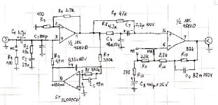
An input coupling cap, an elco that seems part of a filter, a servo around the input stage - all this is a bit strange to say the least
R12 should be 1k5, R9 left pin should be connected to ground instead the 4580 output. And this is only for a start
Hello,
a few pics of the Phono Box:
http://home.arcor.de/bauer77/_private/project_phono_box.htm
Enjoy the overlay picture!
Stefan
a few pics of the Phono Box:
http://home.arcor.de/bauer77/_private/project_phono_box.htm
Enjoy the overlay picture!
Stefan
Modding the phonobox?
Hello!
I'm thinking about modding or improving the Phonobox.
I have some OPA604, 134 and 637 in my box, are they drop-in replacements?
There are some ceramic caps on the card, too. And elcos

Earlier some people suggested there were some "faults" in the circuit, is there anything one can do?
What about increasing the output level a bit?
Got some experience with modding CD:s so difficult jobs don't scare me - I totally lack theoretical skills, but understand schematics, so if ou can help me - thanx!
Tom
Hello!
I'm thinking about modding or improving the Phonobox.
I have some OPA604, 134 and 637 in my box, are they drop-in replacements?
There are some ceramic caps on the card, too. And elcos
Earlier some people suggested there were some "faults" in the circuit, is there anything one can do?
What about increasing the output level a bit?
Got some experience with modding CD:s so difficult jobs don't scare me
- I totally lack theoretical skills, but understand schematics, so if ou can help me - thanx!Tom
Dimitri do not talk in puzzled way, because....
http://www.angelfire.com/az3/dimitri/images/phonobox.pdf
http://www.angelfire.com/az3/dimitri/images/phonobox.pdf

Good morning Dio!
Looks cool!
Did you replace the opamps or any other capacitors? If you did the mods above (or other mods), what effect did it have on the sound?
Cheers,
Tom
Looks cool!
Did you replace the opamps or any other capacitors? If you did the mods above (or other mods), what effect did it have on the sound?
Cheers,
Tom
I replace:
R12 with 1,5kohm
R10 with 220 ohm
C1 with 1mF WIMA MKS4
cut R9 from mass
put 10microF and 100nF near OP-amps
Replace filter capacitors with 2200 microF
bypass regulators with 100nF
R12 with 1,5kohm
R10 with 220 ohm
C1 with 1mF WIMA MKS4
cut R9 from mass
put 10microF and 100nF near OP-amps
Replace filter capacitors with 2200 microF
bypass regulators with 100nF
Re: Modding the phonobox?
Just about everything in the Phonobox is either wrong or just stupid and wasteful engineering. Just what went on in the mind of the 'designer' is something I can not grasp, when it is perfectly possible to make with 50% of the parts and just two 5534 opamps something that outperforms this one easily.
Keeping the circuit and dropping in expensive opamps and capacitors makes things only worse, as such parts should be put to better use.
Dimitri goes some way to redressing the circuit errors present.
I would go further: throw away the innards, keep the box and the power supply, and put in any of the simple opamp-based phono circuits that circulate here on the forum.
A DC servo fed back to the cartridge input ... sjeeeez ....
Zombie said:
Earlier some people suggested there were some "faults" in the circuit, is there anything one can do?
Just about everything in the Phonobox is either wrong or just stupid and wasteful engineering. Just what went on in the mind of the 'designer' is something I can not grasp, when it is perfectly possible to make with 50% of the parts and just two 5534 opamps something that outperforms this one easily.
Keeping the circuit and dropping in expensive opamps and capacitors makes things only worse, as such parts should be put to better use.
Dimitri goes some way to redressing the circuit errors present.
I would go further: throw away the innards, keep the box and the power supply, and put in any of the simple opamp-based phono circuits that circulate here on the forum.
A DC servo fed back to the cartridge input ... sjeeeez ....
mass=ground
I don't replace OPamps.
It's possible to replace JRC4580 with better dual ultra-low noise OP maybe OPA2227 or something...
I don't replace OPamps.
It's possible to replace JRC4580 with better dual ultra-low noise OP maybe OPA2227 or something...
Stupid thing
This preamp comes not from fa Project, but from my friend Dr. Sýkora and I was the first, which was build it. In original was there two NE 5534 and in servo loop TL 071. As input cap was there foil polyester, any bipolar. This connection is about sixteen years old and was designed ASAP cheapest. When it was new, in many comparisions every win against all preamps in tests. Later it was published in one Czech electronic magazine and was ( and still is ) in our country very popular. Probably from this magazine it was stealed by fa Project and later reduciert to the form, which show Dimitri. This amp is very simple, but have very good sound and noise parameters thanks to " active damping " ( very low current noise ). Dr. Sýkora is not fool - to this time he develope many better preamps - in this time he's working for fa Clearaudio.
This preamp comes not from fa Project, but from my friend Dr. Sýkora and I was the first, which was build it. In original was there two NE 5534 and in servo loop TL 071. As input cap was there foil polyester, any bipolar. This connection is about sixteen years old and was designed ASAP cheapest. When it was new, in many comparisions every win against all preamps in tests. Later it was published in one Czech electronic magazine and was ( and still is ) in our country very popular. Probably from this magazine it was stealed by fa Project and later reduciert to the form, which show Dimitri. This amp is very simple, but have very good sound and noise parameters thanks to " active damping " ( very low current noise ). Dr. Sýkora is not fool - to this time he develope many better preamps - in this time he's working for fa Clearaudio.
Hello Upopa!
Very interesting information. Have you got a link to the original schematic?
Have you tried to "restore" the phonobox to the original Sykora?
Cheers,
Tom
Very interesting information. Have you got a link to the original schematic?
Have you tried to "restore" the phonobox to the original Sykora?
Cheers,
Tom
Stupid thing, part two
To Zombie : " restoration " is easy. Resolder both opamps and get there precidip sockets. If is PCB made for dual opamp, get there NE 5532 and instead 061 give 071 ( or AD 711, LF 411 etc. - any low noise JFet opamp with low offset ). Change input cap, get there PP or PES with the same value. With NE 553. family of opamps is SNR of this connection in MM mode better than 86 dB, which is 1 dB up theoretical value of noise of typical MM pickup ( 85 dB ). This preamp is noise optimalised for MM pickups, in MC mode is it " only " 68 dB ( noise floor is refered to 5 mV and 0,5 mV ). Value of others devices stay the same, but on output give serial resistor 100 R for better stability. That's all. Now exist better solutions, I will try to get it on this pages - it is not exist in electronic form. 😎
To Zombie : " restoration " is easy. Resolder both opamps and get there precidip sockets. If is PCB made for dual opamp, get there NE 5532 and instead 061 give 071 ( or AD 711, LF 411 etc. - any low noise JFet opamp with low offset ). Change input cap, get there PP or PES with the same value. With NE 553. family of opamps is SNR of this connection in MM mode better than 86 dB, which is 1 dB up theoretical value of noise of typical MM pickup ( 85 dB ). This preamp is noise optimalised for MM pickups, in MC mode is it " only " 68 dB ( noise floor is refered to 5 mV and 0,5 mV ). Value of others devices stay the same, but on output give serial resistor 100 R for better stability. That's all. Now exist better solutions, I will try to get it on this pages - it is not exist in electronic form. 😎
- Status
- Not open for further replies.
- Home
- Source & Line
- Analogue Source
- Schematic for Pro-ject phono box