My two best audio forums, this one and AudioKarma. I'm both a fan/collector of vintage audio gear and a DIY guy with an electronics background out of college many moons ago. . . so both forums are really interesting and very information. DIYAudio in particular to feed my DIY fix. I'm working on a Peter Daniels gainclone but waiting to get that one right so that it will be my perfect reference unit. In the meantime, other gainclones and, t-amps, etc.
I posted most of the following in the other forum but no help yet. Perhaps this is the more appropriate forum for my issue.
Last year I bought an LXI Receiver (sold by Sears but all Sanyo boards) RE-1085 for $5. It was too far gone with too many problems. So now it is an organ donater. It is living again through other units & projects . . . the knobs, transformers, etc. I'm trying to salvage the pre-amp board and the RCA input board for the RIAA phono pre-amp to use as a pre-amp to a gainclone project.
Pre-amp - Has bass, mid, treble and vol/bal. I've traced the pre-amp (not the RIAA pre yet) and have a good picture of its topography. I'm getting hung up on the output connections and power supply rails. I know this area should be the easiest to reverse engineer but am having some difficulties. Can anyone help me with the complete schematic . . . anyone have it? I searched, and searched and come up empty so far.
RIAA phono pre - this section is nicely congregated near the phono inputs of the RCA input board. There are two 5 pin ICs (IC151, IC152) both labeled "ML120 1301". Again searched and searched and can't find anything on this. Does anyone know what this is. I suspect it is some kind of opamp.
If anyone has or can provide a schematic this would be very helpful. as it would be a shame not to be able to re-use these two modules. I'm almost there but not quite.
I will post the preamp schematic that I traced in the next post. Pictures hopefully soon.
Thanks in advance.
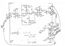
Schematic
So, after several hours over a few evenings, below is the preamp schematic. One channel fully traced, the other just the I/O sections. This is pretty accurate, hopefully minimizing tracing errors. Not fully analyzed but looks like a usable 3 tone control with vol/bal pre-amp circuit. Having problems understanding the volume control circuit where both ends of the dual pot go to another board (white wires on CS-14 and CS-15).
What about the power rails? It appears as a single ended supply with +VDC and ground. Is this correct or am I missing, not seeing something here. And why does it enter the board through R256 (I haven't measured the value)? What would be the suspected voltage(s). +12V?
If the image is not clear, I'll re-up.
Again, hanks in advance.
Attachments
From what you describe of the phono section with the SIL ICs, your PCBs sound similar to the ones in a Sanyo JCX2400K I have.
Can you post pics of the boards?
Gary
Can you post pics of the boards?
Gary
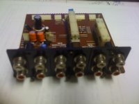
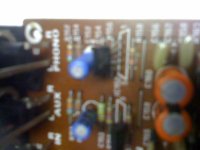
LXI Phono section pictures
Below are pictures of the phono section. I apologies for the blurryness as they were taken with my iphone up close (and it doesn't do up close well).
Below are pictures of the phono section. I apologies for the blurryness as they were taken with my iphone up close (and it doesn't do up close well).
Attachments
Last edited:
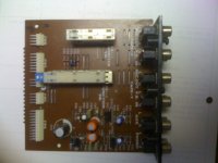
LXI Phono section pictures
Some more pictures:
(Again very sorry for the blurry shots).
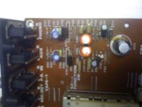
Edit: Closeup (poor) of the 5 pin SIL which I suspect might be an opamp. I have spend many hours searching on the net but cannot find this device.
Some more pictures:
(Again very sorry for the blurry shots).
Edit: Closeup (poor) of the 5 pin SIL which I suspect might be an opamp. I have spend many hours searching on the net but cannot find this device.
Attachments
Last edited:
- Status
- Not open for further replies.