Hi all,
I have a bunch of these Russian tubes lying around and it's about time to put them at work.
According to the datasheets,they're equivalent to EL82...but not quite.
Anyone use them and how?Comments,results?
I'm especially interested in a possible implementation in stabilized HT PS circuits.
TIA!
I have a bunch of these Russian tubes lying around and it's about time to put them at work.
According to the datasheets,they're equivalent to EL82...but not quite.
Anyone use them and how?Comments,results?
I'm especially interested in a possible implementation in stabilized HT PS circuits.
TIA!

It looks quite nice at a plate voltage and idle current that will make it melt... 🙂 Beyond that, vertical deflection tubes are generally what I would call *USEFUL. Last amp I built with 25HX5 as the front end amplifiers for larger sweep finals. Quite happy with it.
Pentodes only need apply...
Douglas
Pentodes only need apply...
Douglas
There are data sheets for both, if that helps.
6P18P - https://frank.pocnet.net/sheets/113/6/6P18P.pdf
Pa = 12W max
Pg2 = 2.5W max
Va and Vg2 = 250V max
gm = 11mA/V
ra = 22k ohms
According to a few replies back when I was searching for info on 6P43P, that one is the Russian version of EL86. https://frank.pocnet.net/sheets/129/e/EL86.pdf
Pa = 12W max
Pg2 = 1.75W max
Va and Vg2 = 250V max
gm = 11mA/V
ra = 26k ohms
Yep, those two look pretty close!
My understanding is that 6P15P is the Russian EL83 - similar to EL84 but with lower max plate dissipation and a lower dissipation g2. The Soviet data sheet says mu = 25.
https://frank.pocnet.net/sheets/113/6/6P15P.pdf
If 6P18P triode mu is up around 12, that would be a bit higher than 6P43P-E in triode. Thanks for that bit of info, I missed that.
https://frank.pocnet.net/sheets/113/6/6P15P.pdf
If 6P18P triode mu is up around 12, that would be a bit higher than 6P43P-E in triode. Thanks for that bit of info, I missed that.
I see the same plate dissipation for 6P15P and 6BQ5 (Pa=12watts) and higher Va =330V and higher Vg2=330V- similar to EL84 but with lower max plate dissipation …
6P14P is the Russian version of EL84/6BQ5.
Russian 6P14P data sheet claims Pa = 14W and Pg2 = 2.2W, Va and Vg2 max = 300V.
https://frank.pocnet.net/sheets/113/6/6P14P.pdf
Mullard EL84 data sheet claims Pa = 12W and Pg2 = 2W, Va and Vg2 max = 300V.
https://frank.pocnet.net/sheets/129/e/EL84.pdf
I guess there are some minor differences, variances between Western and Russian versions.
I suppose mu and max Va/Vg2 would be the characteristics that differentiate these different pentodes.
EL84 - 11.3 mA/V (Va, Vg2 = 250V, Ia+Ig2 = 53.5mA)
6P14P - 11.3mA/V (Va, Vg2 = 250V, Ia+Ig2 = 53mA)
6P15P - 15mA/V (Va = 300V, Vg2 = 150V, Ia+Ig2 = 34.5mA)
EL83 - 10mA/V (Va, Vg2 = 250V, Ia+Ig2 = 41mA)
6P18P - 11mA/V (Va, Vg2 = 180V, Ia+Ig2 = 61mA)
EL86 (=6P43P?) - 11mA/V (Va, Vg2 = 170V, Ia+Ig2 = 73.5mA)
6BQ5, EL84, 6P15P, EL83 have triode mu around 19 to 24, Va and Vg2 max of around 300V.
6P18P, EL86, 6P43P have triode mu around 8 to 12. Lower Va and Vg2 max of around 250V.
Last edited:
@rongon,
Thanks for the handy comparative table; apparently it’s purpose is to show S (mu) at a specific operating condition. Just to be sure it is understood correctly, take for example:
6P15P - 15mA/V (Va = 300V, Vg2 = 150V, Ia+Ig2 = 34.5mA)
Does this datum show mu is at 15mV/V when the 6P15P is biased such that Ia+Ig2=34.5ma with Va=300V and Vg2=150V? These operating conditions, it is noted, are well below the maxima for this tube.
@FlaCharlie, that participates in DiyA sometimes, argues that wrt die 6BQ5/6P14P family the voltage ratings are guidelines that could be ”stretched” as long as the dissipation ratings are observed. I wondered if this is true for the other tubes in your list. See his post here: https://www.audioasylum.com/audio/tubes/messages/28/285313.html
I was curious about the 6P15P and under which conditions it may serve as a substitute for a 6BQ5-types, now that the once-affordable supply of 6P14Ps is war-diminished. I know that the 6P15P has been mostly dismissed with the caveat that “it has a fragile screen”, but I have not actually seen real-world tests to see if and when the screen burns up in 6BQ5 applications. So, I am currently building (slowly) an amplifier based on Tubelabs SPP PCB but modified to accept EFB biasing scheme and variable plate and screen voltages in Pentode configuration, to test this and to establish some data points for 6P15P use. I have a few 6P18Ps that I might try as well.
Regarding 6CW5/EL86 types, and to add to the notion that maximum plate and screen voltage ratings are “flexible”, @davorin built a amplifier of which he wrote:”I made a guitar amplifier where the output stage uses a pair of 6CW5/EL86 (EI-Niš) at an anode voltage of over 380V. The amplifier works stably with no signs of overheating or oscillation, and the output tubes show no signs of aging despite working at such a high anode voltage.”
https://www.diyaudio.com/community/threads/anyone-ever-use-el86-6cw5.138369/page-3#post-7144386
Last edited:
Re: 6P15P and its allegedly fragile screen...
The best places to look for info on that would the guitar amp forums. Guitar amps often ran EL84s at 350V to 400V on the plate and screen. Apparently replacing the EL84s with 6P15P in those amps resulted in the 6P15P tubes failing.
I have a few 6P15P but I've yet to use them, so I don't actually know.
The example of the 6CW5 running safely at 380v clearly shows that it's the dissipation that really matters. The data lists a maximum plate voltage of 250v and maximum 200v for G2.Regarding 6CW5/EL86 types, and to add to the notion that maximum plate and screen voltage ratings are “flexible”, @davorin built a amplifier of which he wrote:”I made a guitar amplifier where the output stage uses a pair of 6CW5/EL86 (EI-Niš) at an anode voltage of over 380V. The amplifier works stably with no signs of overheating or oscillation, and the output tubes show no signs of aging despite working at such a high anode voltage.”
https://www.diyaudio.com/community/threads/anyone-ever-use-el86-6cw5.138369/page-3#post-7144386
The link says that he's running it at 20mA which is a total dissipation of 7.6w. The data sheet specifies a design center maximum of 12w on the plate and 1.75w on the screen for a total of 13.75w. So he's running the tube at ~55% of its dissipation limit.
As for the 6P15P, I would suggest that if you stay within the published dissipation limits for both the plate and the screen you should be fine. If you're running it in pentode I would suggest that you add a screen stopper resistor which would allow you to measure the current drawn by the screen and adjust the screen voltage so that the limit is not exceeded.
It's my understanding that when a tube is run in triode that the screen dissipation spec can often be ignored. Perhaps others who have used the 6P15P will advise you if that applies with it.
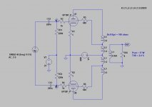
If you want to build tube regulator with 6p18p, I believe these schematics will work:
https://www.aliexpress.com/item/1005001270184823.html
https://www.angelfire.com/planet/funwithtransistors/images/FIG-3-19.gif
https://www.angelfire.com/planet/funwithtransistors/Book_CHAP-3.html
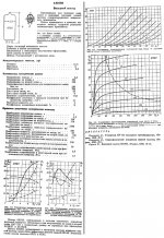
Anyone want to share the model for 6p18p for comparing? Here is my model:
https://www.aliexpress.com/item/1005001270184823.html
https://www.angelfire.com/planet/funwithtransistors/images/FIG-3-19.gif
https://www.angelfire.com/planet/funwithtransistors/Book_CHAP-3.html
Anyone want to share the model for 6p18p for comparing? Here is my model:
Code:
**** 6PI18PI ******************************************
* Created on 10/13/2022 14:26 using paint_kip.jar
* www.dmitrynizh.com/tubeparams_image.htm
* Plate Curves image file: 6pi18pi.png
* Data source link: <plate curves URL>
*----------------------------------------------------------------------------------
.SUBCKT 19 P G2 G K ; LTSpice tetrode.asy pinout
* .SUBCKT 6PI18PI P G K G2 ; Koren Pentode Pspice pinout
+ PARAMS: MU=15.3 KG1=86.39 KP=76.97 KVB=7224.13 VCT=-5.051 EX=0.792 KG2=281.36 KNEE=17.58 KVC=1.571
+ KLAM=1.92E-6 KLAMG=2.795E-5 KNEE2=5.398 KNEX=0.01886  KNK=0.000937 KNG=1.037E-4 KNPL=2.938 KNSL=0.2338 KNPR=24 KNSR=232
+ CCG=3P CGP=1.4P CCP=1.9P VGOFF=-0.6 IGA=0.001 IGB=0.3 IGC=8 IGEX=2
* Vp_MAX=320 Ip_MAX=160 Vg_step=4 Vg_start=0 Vg_count=9
* X_MIN=53 Y_MIN=14 X_SIZE=628 Y_SIZE=644 FSZ_X=1296 FSZ_Y=736 XYGrid=true
* Rp=1400 Vg_ac=20 P_max=12 Vg_qui=-16 Vp_qui=300
* showLoadLine=n showIp=y isDHP=n isPP=n isAsymPP=n isUL=n showDissipLimit=y
* showIg1=y isInputSnapped=y addLocalNFB=n
* XYProjections=n harmonicPlot=y dissipPlot=n
* UL=0.43 EG2=170 gridLevel2=y addKink=y isTanhKnee=y advSigmoid=n
*----------------------------------------------------------------------------------
RE1  7 0  1G    ; DUMMY SO NODE 7 HAS 2 CONNECTIONS
E1   7 0  VALUE=  ; E1 BREAKS UP LONG EQUATION FOR G1.
+{V(G2,K)/KP*LOG(1+EXP((1/MU+(VCT+V(G,K))/SQRT(KVB+V(G2,K)*V(G2,K)))*KP))}
RE2  6 0  1G    ; DUMMY SO NODE 6 HAS 2 CONNECTIONS
E2  6 0  VALUE={(PWR(V(7),EX)+PWRS(V(7),EX))} ; Kg1 times KIT current
RE21 21 0 1
E21  21 0 VALUE={V(6)/KG1*ATAN((V(P,K)+KNEX)/KNEE)*TANH(V(P,K)/KNEE2)} ; Ip with knee but no slope and no kink
RE22 22 0 1 ; E22: kink curr deviation for plate
E22  22 0 VALUE={V(21)*LIMIT(KNK-V(G,K)*KNG,0,0.3)*(-ATAN((V(P,K)-KNPL)/KNSL)+ATAN((V(P,K)-KNPR)/KNSR))}
G1   P  K  VALUE={V(21)*(1+KLAMG*V(P,K))+KLAM*V(P,K) + V(22)}
* Alexander Gurskii screen current, see audioXpress 2/2011, with slope and kink added
RE43 43 K 1G ; Dummy
E43  43 G2 VALUE={0} ; Dummy
G2   43 K  VALUE={V(6)/KG2*(KVC-ATAN((V(P,K)+KNEX)/KNEE)*TANH(V(P,K)/KNEE2))/(1+KLAMG*V(P,K))-V(22)}
RCP  P K  1G     ; FOR CONVERGENCE
C1   K G  {CCG}  ; CATHODE-GRID 1
C2   G P  {CGP}  ; GRID 1-PLATE
C3   K P  {CCP}  ; CATHODE-PLATE
RE23 G 0 1G
GG G K VALUE={(IGA+IGB/(IGC+V(P,K)))*(MU/KG1)*
+(PWR(V(G,K)-VGOFF,IGEX)+PWRS(V(G,K)-VGOFF,IGEX))}
.ENDS
*$
Attachments


Here.I'm especially interested in a possible implementation in stabilized HT PS circuits.
Attachments

If you want to build tube regulator with 6p18p, I believe these schematics will work:
https://www.aliexpress.com/item/1005001270184823.html
https://www.angelfire.com/planet/funwithtransistors/images/FIG-3-19.gif
https://www.angelfire.com/planet/funwithtransistors/Book_CHAP-3.html
Anyone want to share the model for 6p18p for comparing? Here is my model:
Code:**** 6PI18PI ****************************************** * Created on 10/13/2022 14:26 using paint_kip.jar * www.dmitrynizh.com/tubeparams_image.htm * Plate Curves image file: 6pi18pi.png * Data source link: <plate curves URL> *---------------------------------------------------------------------------------- .SUBCKT 19 P G2 G K ; LTSpice tetrode.asy pinout * .SUBCKT 6PI18PI P G K G2 ; Koren Pentode Pspice pinout + PARAMS: MU=15.3 KG1=86.39 KP=76.97 KVB=7224.13 VCT=-5.051 EX=0.792 KG2=281.36 KNEE=17.58 KVC=1.571 + KLAM=1.92E-6 KLAMG=2.795E-5 KNEE2=5.398 KNEX=0.01886 KNK=0.000937 KNG=1.037E-4 KNPL=2.938 KNSL=0.2338 KNPR=24 KNSR=232 + CCG=3P CGP=1.4P CCP=1.9P VGOFF=-0.6 IGA=0.001 IGB=0.3 IGC=8 IGEX=2 * Vp_MAX=320 Ip_MAX=160 Vg_step=4 Vg_start=0 Vg_count=9 * X_MIN=53 Y_MIN=14 X_SIZE=628 Y_SIZE=644 FSZ_X=1296 FSZ_Y=736 XYGrid=true * Rp=1400 Vg_ac=20 P_max=12 Vg_qui=-16 Vp_qui=300 * showLoadLine=n showIp=y isDHP=n isPP=n isAsymPP=n isUL=n showDissipLimit=y * showIg1=y isInputSnapped=y addLocalNFB=n * XYProjections=n harmonicPlot=y dissipPlot=n * UL=0.43 EG2=170 gridLevel2=y addKink=y isTanhKnee=y advSigmoid=n *---------------------------------------------------------------------------------- RE1 7 0 1G ; DUMMY SO NODE 7 HAS 2 CONNECTIONS E1 7 0 VALUE= ; E1 BREAKS UP LONG EQUATION FOR G1. +{V(G2,K)/KP*LOG(1+EXP((1/MU+(VCT+V(G,K))/SQRT(KVB+V(G2,K)*V(G2,K)))*KP))} RE2 6 0 1G ; DUMMY SO NODE 6 HAS 2 CONNECTIONS E2 6 0 VALUE={(PWR(V(7),EX)+PWRS(V(7),EX))} ; Kg1 times KIT current RE21 21 0 1 E21 21 0 VALUE={V(6)/KG1*ATAN((V(P,K)+KNEX)/KNEE)*TANH(V(P,K)/KNEE2)} ; Ip with knee but no slope and no kink RE22 22 0 1 ; E22: kink curr deviation for plate E22 22 0 VALUE={V(21)*LIMIT(KNK-V(G,K)*KNG,0,0.3)*(-ATAN((V(P,K)-KNPL)/KNSL)+ATAN((V(P,K)-KNPR)/KNSR))} G1 P K VALUE={V(21)*(1+KLAMG*V(P,K))+KLAM*V(P,K) + V(22)} * Alexander Gurskii screen current, see audioXpress 2/2011, with slope and kink added RE43 43 K 1G ; Dummy E43 43 G2 VALUE={0} ; Dummy G2 43 K VALUE={V(6)/KG2*(KVC-ATAN((V(P,K)+KNEX)/KNEE)*TANH(V(P,K)/KNEE2))/(1+KLAMG*V(P,K))-V(22)} RCP P K 1G ; FOR CONVERGENCE C1 K G {CCG} ; CATHODE-GRID 1 C2 G P {CGP} ; GRID 1-PLATE C3 K P {CCP} ; CATHODE-PLATE RE23 G 0 1G GG G K VALUE={(IGA+IGB/(IGC+V(P,K)))*(MU/KG1)* +(PWR(V(G,K)-VGOFF,IGEX)+PWRS(V(G,K)-VGOFF,IGEX))} .ENDS *$
Hey Koonw, thank you for this.
Unfortunately, I'm getting errors running the 6PI18PI model. I must be doing something wrong.
Here's the .asy symbol file I'm using to place the above into LTspice. Can you see a mistake in there?
(Sorry to go off-topic this way...)
Code:
*** NOT WORKING IN MY SYSTEM***
*
Version 4
SymbolType CELL
LINE Normal -48 0 -48 16
LINE Normal 48 0 48 16
LINE Normal 0 -48 0 -16
LINE Normal -20 -16 20 -16
LINE Normal -20 -12 20 -12
LINE Normal -20 -16 -20 -12
LINE Normal 20 -16 20 -12
LINE Normal 48 0 28 0
LINE Normal 20 0 12 0
LINE Normal 4 0 -4 0
LINE Normal -12 0 -20 0
LINE Normal -28 0 -36 0
LINE Normal -48 16 -28 16
LINE Normal -20 16 -12 16
LINE Normal -4 16 4 16
LINE Normal 12 16 20 16
LINE Normal 28 16 36 16
LINE Normal -24 28 24 28
LINE Normal -32 64 -32 36
LINE Normal -24 28 -32 36
LINE Normal 24 28 32 36
LINE Normal -28 32 28 32
ARC Normal -48 -48 48 48 48 0 -48 0
ARC Normal -48 -32 48 64 -48 16 48 16
WINDOW 0 8 -64 Left 0
WINDOW 3 -24 80 Left 0
SYMATTR Value 6PI18PI
SYMATTR Prefix X
SYMATTR SpiceModel 6P18P_KW.inc ; correct file name in my system
SYMATTR Value2 6PI18PI
PIN 0 -48 NONE 0
PINATTR PinName 1 ; P
PINATTR SpiceOrder 1
PIN 48 0 NONE 0
PINATTR PinName 2 ; G2
PINATTR SpiceOrder 2
PIN -48 16 NONE 0
PINATTR PinName 3 ; G
PINATTR SpiceOrder 3
PIN -32 64 NONE 0
PINATTR PinName 4 ; K
PINATTR SpiceOrder 4
Thanks.
Remove "*" at the very top line if any, i.e. let it begins with "Version 4", it's tetrode symbol, it displayed correctly.
The actual .asy file does not have those remarks at the beginning. I.e., it starts with "Version 4".
When I run the simulation, I get error:
Unknown subcircuit called in:
xu3 p1 n002 n005 n006 6p18p
I've attached the .asc in which I'm using the 6P18P model.
When I run the simulation, I get error:
Unknown subcircuit called in:
xu3 p1 n002 n005 n006 6p18p
I've attached the .asc in which I'm using the 6P18P model.
Attachments
In the 6p18p model, 1st line
.SUBCKT 19 P G2 G K ; LTSpice tetrode.asy pinout
Change to:
.SUBCKT 6p18p P G2 G K ; LTSpice tetrode.asy pinout
.SUBCKT 19 P G2 G K ; LTSpice tetrode.asy pinout
Change to:
.SUBCKT 6p18p P G2 G K ; LTSpice tetrode.asy pinout
- Home
- Amplifiers
- Tubes / Valves
- Russian 6Pi18Pi/6∏18∏ - any use?