After i started to repair vintage amps and building some diy amp projects , both tube and solid state. i have started getting a big interest in different types of amplifier designs,
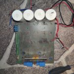
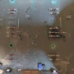
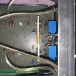
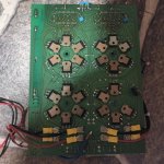
A week ago i got my hands on a norwegian made amplifier that was in a need of repair, a Doxa Signature MK1 . and i saw right away that this amp had a unusual design, after some searching i found out this type of design is called Rush Cascode and no tail pair.
I have searched to find more power amps with similar design but i have not found something similar
So, have any of you guys seen a similar design , diy or commercial built?
i add the schematic i found online to this post , its not 100% correct but most the essential parts is correct.
i will reverse engineer it and make a complete and correct design at a later time if there is interest.
I wonder what Nelson thinks about this type of design, fun to hear his opinion too.
Attachments
Last edited:
The global feedback does not appear to be correctly drawn.
I have never before seen the bias network (Vbe multiplier) applied so many stages before the output. I don't expect this amplifier to have good control over the output bias current.
Ed
I have never before seen the bias network (Vbe multiplier) applied so many stages before the output. I don't expect this amplifier to have good control over the output bias current.
Ed
A Vbe multiplier (Q13, Q12) with a current source (Q22) and a load (R9), setting the dc current of Q11, Q20 (what is R8 doing?), which set the currents through current sources Q4, Q21 to create the 'rush'-structure. rail noise enters through R3, R40, and cannot be improved (topology). Seven semiconductors for what?
The adjustment of balancing the currents of Q4, Q21 is ridiculous (P1//R2 vs R39): almost everything stuck on the pos rail I bet.
When there is an input signal, changes are that Q5, Q19 go into class B mode (R10, R32).
How is the output offset voltage managed? No control, no feedback save R43 (odd, no counterpart under R23) and R31 (#3 is right!) which cannot 'help' Q19 but inteferes with Q23, pulling everything out of balance again.
R21, (C1), R22 in parallel, why this 345k?
Doxa???
In general, I've the impression that this is an AI generated circuit drawing, but has nothing to do with DIYaudio in reality.
I've also the impression that, based upon numerous designs, mr Pass prefers more simpler & elegant topologies - less is more.
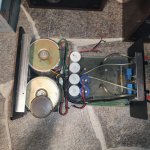
Like i wrote in the beginning, the scematic is not 100% correct, it has alot of things that are not wired correctly , but some of it is correct. This is the amp in real life.