Just for grins, I downloaded Akabak. Won't run. Compatibility problems. I have W7/64-bit. Akabak is 16-bit. I tried compatibility all the way back to W95. No joy. Any hints?
Bob
Bob
If you have Win 7 prof or enterprise, install Win XP virtual machine then install Akabak inside that. Otherwise get an old 32 bit vista or xp machine and play with it there. Very powerful program but could use a port to a modern os.
snip
Otherwise get an old 32 bit vista or xp machine and play with it there.
I have an old flea powered XP32 netbook which has no trouble at all running Akabak. It dates from the days before bloatware so is pretty easy on system resources.
feedblakk
I second x's suggestion of "Windows XP Mode". It's a free download from Microsoft. It's the easiest way of running old software that doesn't like 64-bit mode.
The "XP mode" is actually a copy of 32-bit Windows XP, all set up in its own VM. There's one gotcha when using it with AkAbak: In a VM, the host computer's hard disk appears as a network share, and AkAbak is not network aware. So you need to install AkAbak within the VM image, and manually copy any required input / output files in/out of the VM.
The "XP mode" is actually a copy of 32-bit Windows XP, all set up in its own VM. There's one gotcha when using it with AkAbak: In a VM, the host computer's hard disk appears as a network share, and AkAbak is not network aware. So you need to install AkAbak within the VM image, and manually copy any required input / output files in/out of the VM.
Within XP Virtual machine you can copy the plot bitmap a to the copy and paste buffer that transcends both the VM and the real machine to enable input of text files and output of bitmap files quickly and easily without using network drives. I opened up the web browser inside the VM and downloaded AkAbak straight into the VM in order to install it. There is another catch: VM is only available with Pro or Enterprise versions and not home or home premium versions of Win 7.
It runs in W7 with XP virtual machine installed. Kind of like Wine. Does Wine require a real Windows license or is it really free?
Wine is free. It's not a full OS, more like a translation layer (Win32 system calls to Linux equivalents). It's commonly called an emulator, but Wine is a recursive acronym specifically denying that ("Wine Is Not an Emulator"). 🙂
Has someone actually gotten Akabak to run in Wine?
Yes. No problem.
I don't know how to use it at all, but it installs and runs perfectly as far as I can tell. 🙂
Cogitech,
Do you speak linux? I tried to load Wine on an Ubuntu computer but failed. Chose linux because they are virtually virus free, and my main computer is Mac. I want to start to do my own simulations and cabinet calculations, but there is nada for Macs.
JH
Do you speak linux? I tried to load Wine on an Ubuntu computer but failed. Chose linux because they are virtually virus free, and my main computer is Mac. I want to start to do my own simulations and cabinet calculations, but there is nada for Macs.
JH
This is a great case for buying a refurbished circa 2004 laptop for $140 loaded with Windows xp. These are great machines I used to use at work. Rakuten.com - Dell Latitude D600 Laptop, Refurbished - Intel Pentium M 745, 512MB DDR, 40GB HDD, CD-RW/DVD Combo, Windows XP Home
Modeling a Double-Uneven-Length BLH with AkAbak
Ever since I have been working on the Cornu horn with its double uneven length horn segments, I have been curious about how to design one from scratch. The idea is that the two horn lengths will have offset resonances such that the combined output has a smoother frequency response. I wanted to do it using a single driver rather than two separate drivers and two separate horns. This is where it gets tricky because when you combine horns with a single common chamber and throat, there are non-linear interactions. Luckily, AkAbak can handle all of this.
I needed a good design for a single BLH to start with and since I had just modeled the very nice BK12 horn as a rear firing BLH, I decided to start there. I am using the geometry of the horn from the BK12, but modified the driver chamber to a smaller volume to accommodate the FF105WK driver which has more xmax.
The model of the horn has 8 segments (see code section below). The first segment is the throat from the driver chamber and last segment is the mouth opening.
First I doubled up the horn paths splitting them off right after the initial 1 in throat section into two equal paths. After doing this, I ran the sim to see if it matches the original single horn to double check for any errors in setting up the geometry.
Then I went in and slowly started reducing some of the key length segments of the second horn and observed the frequency response. I found that in the two longest segments, by reducing the length of the second horn (segment 2 by 5 inches, and segment 6 by 3 inches), it started to produce some offset overlaps that should help smooth the response.
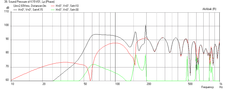
I also found that if I increased the mouth of the original horn by 1 inch and increased the length of segment 8 (mouth) by 1.5 inches, it helped to balance out the SPL levels between horns 1 and 2 and filled in a rather big dip that was there before.
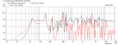
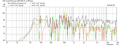
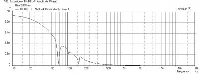
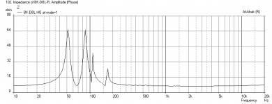
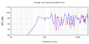
Anyhow, plotted below are the results: first plot is the original single horn combined driver + horn (black) & horn only (red), second plot is the uneven length double horn with combined (black) & horn 1 (red) horn 2 (green), the cone displacement, the impedance, and a plot of both responses superimposed.
The tradeoff of smoothness is less bass extension.
Ever since I have been working on the Cornu horn with its double uneven length horn segments, I have been curious about how to design one from scratch. The idea is that the two horn lengths will have offset resonances such that the combined output has a smoother frequency response. I wanted to do it using a single driver rather than two separate drivers and two separate horns. This is where it gets tricky because when you combine horns with a single common chamber and throat, there are non-linear interactions. Luckily, AkAbak can handle all of this.
I needed a good design for a single BLH to start with and since I had just modeled the very nice BK12 horn as a rear firing BLH, I decided to start there. I am using the geometry of the horn from the BK12, but modified the driver chamber to a smaller volume to accommodate the FF105WK driver which has more xmax.
The model of the horn has 8 segments (see code section below). The first segment is the throat from the driver chamber and last segment is the mouth opening.
First I doubled up the horn paths splitting them off right after the initial 1 in throat section into two equal paths. After doing this, I ran the sim to see if it matches the original single horn to double check for any errors in setting up the geometry.
Then I went in and slowly started reducing some of the key length segments of the second horn and observed the frequency response. I found that in the two longest segments, by reducing the length of the second horn (segment 2 by 5 inches, and segment 6 by 3 inches), it started to produce some offset overlaps that should help smooth the response.
I also found that if I increased the mouth of the original horn by 1 inch and increased the length of segment 8 (mouth) by 1.5 inches, it helped to balance out the SPL levels between horns 1 and 2 and filled in a rather big dip that was there before.
Anyhow, plotted below are the results: first plot is the original single horn combined driver + horn (black) & horn only (red), second plot is the uneven length double horn with combined (black) & horn 1 (red) horn 2 (green), the cone displacement, the impedance, and a plot of both responses superimposed.
The tradeoff of smoothness is less bass extension.
Code:
| Define Horn Segments (need to multiply by Width for area): S_Throat, S_Mouth, Length

| Shared Throat Segment

	S1T=1.00*0.0254;	S1M=2.32*0.0254;	L1=1.00*0.0254;

| First Horn

 	S2T=2.32*0.0254;	S2M=4.90*0.0254;	L2=12.52*0.0254;
	S3T=4.90*0.0254;	S3M=4.91*0.0254;	L3=2.19*0.0254;
	S4T=4.91*0.0254;	S4M=4.92*0.0254;	L4=2.77*0.0254;
	S5T=4.92*0.0254;	S5M=4.93*0.0254;	L5=2.19*0.0254;
	S6T=4.93*0.0254;	S6M=11.72*0.0254;	L6=18.33*0.0254;
	S7T=11.72*0.0254;	S7M=13.50*0.0254;	L7=4.90*0.0254;
	S8T=13.50*0.0254;	S8M=15.51*0.0254;	L8=8.75*0.0254;  | Enlarge mouth on Horn 1 by 2 in, extend length by 1.5 in

| Second Horn

 	S2T2=2.32*0.0254;	S2M2=4.90*0.0254;	L22=7.52*0.0254; | Reduced by 5 in
	S3T2=4.90*0.0254;	S3M2=4.91*0.0254;	L32=2.19*0.0254;
	S4T2=4.91*0.0254;	S4M2=4.92*0.0254;	L42=2.77*0.0254;
	S5T2=4.92*0.0254;	S5M2=4.93*0.0254;	L52=2.19*0.0254;
	S6T2=4.93*0.0254;	S6M2=11.72*0.0254;	L62=15.33*0.0254; | Reduced by 3 in
	S7T2=11.72*0.0254;	S7M2=13.50*0.0254;	L72=4.90*0.0254;
	S8T2=13.50*0.0254;	S8M2=13.51*0.0254;	L82=7.24*0.0254;
Attachments
Last edited:
AkAbak sim of Cornu with 4 horns and wall/floor
I just simulated the Cornu with comprehensive boundary conditions for the wall/floor and proper orientation and position of horn mouths in the Cornu thread here: http://www.diyaudio.com/forums/full-range/225622-ever-think-building-cornu-spiral-horn-now-you-can-88.html#post3504049
As expected it is a real bass amplifying cabinet that has probably too much upper bass in the 150 to 250 Hz region.
AkAbak sim of Karlson K15
This is the most complex model I have done with AkAbak and from what I am told, it seems to be fairly close to how a real Karlson behaves. One can now scale a Karlson box and see the effect on frequency response.
http://www.diyaudio.com/forums/full-range/213594-karlson-10.html#post3528706
Here is an original 1955 K15 fitted with a Betsy K driver.
Cogitech,
Do you speak linux? I tried to load Wine on an Ubuntu computer but failed. Chose linux because they are virtually virus free, and my main computer is Mac. I want to start to do my own simulations and cabinet calculations, but there is nada for Macs.
JH
Sorry for the delay. Not around much these days.
To get WINE installed simply open a command-prompt and do:
It'll prompt you for your password and once entered it will proceed to update your sources and then download and install WINE, with all dependencies satisfied.sudo apt-get update && sudo apt-get install wine
P.S. in my experience, using Akabak is far more difficult than getting it installed in WINE. 😀
I just installed VirtualBox (free VM from Oracle) on my Win7 64-bit Home. Win XP is installed in the VM for Akabak. It runs smoothly. Seamless windows mode allows me to have Akabak window appearing in Win7 desktop.
Thanks for the tip on VM from Oracle. I was looking for a free VM for Win 7 home - I will give it a try.
You are welcome! I almost upgraded my Win7 Home to Win 7 Pro. or purchased VMware for running Akabak. Saved some money for the new year.
xrk,
Got my Akabak to run in Wine on my Linux machine. Found some pretty good tutorials at:
www.avsforum.com/forum/...speakers.../1258118-akabak-dummies.html
I love MLTL designs because of the ease of construction with a good result. Tried your accidental MLTL method and would like confirmation from Akabak.
Problem: When I define the enclosure, should it be a standard vented enclosure or a wave guide enclosure that also has a vent?
Would it be possible for you to share a MLTL script from Akabak, so that I could plug in my own dimensions?
Last edited:
- Status
- Not open for further replies.
- Home
- Loudspeakers
- Full Range
- Running Akabak