Hello everyone,
I recently purchased a used Rotel RB1080. Its in good working order, but i did some advance prep, just to get to know in general the topology and how it worked. I was able to find a service manual, and after cleaning up a bit, decided to check the bias.
I found that my channel boards had a pretty different layout than the service manual, so was a little reticent to get too into it. I do a decent amount of building, but mostly studio audio and guitar amps, and mostly tube designs. I can read a schematic and have enough transistor knowledge to diagnose fundamental problems, but don't have a lot of experience in the HIFI world.
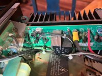
I've attached some info from the manual as well as a pic of the left channel front end. There should be two test points, TP1 and TP3 on the upper left corner. On mine they are not there. There is a resistor, R653(.22r) that parallels what should be TP1 and TP3, so I am assuming that should be the right place to test. On the PCB there is marking for TP1 right above this resistor with a line to either side of the resistor.
When I hooked my meter up to either side of R653, I got 3.5mV on both channels. I found that strange, and wonder if there was some reason it was biased to this as opposed to 7mV. I went ahead and biased both sides to 7mV. Amp sounds good, but I don't have a way of testing whether it's operating correctly.
I emailed Rotel with the serial number to see if they had a more accurate service manual with proper layout, but thought it might be worth posting here as well.
Anybody have any knowledge of these?
Ian
I recently purchased a used Rotel RB1080. Its in good working order, but i did some advance prep, just to get to know in general the topology and how it worked. I was able to find a service manual, and after cleaning up a bit, decided to check the bias.
I found that my channel boards had a pretty different layout than the service manual, so was a little reticent to get too into it. I do a decent amount of building, but mostly studio audio and guitar amps, and mostly tube designs. I can read a schematic and have enough transistor knowledge to diagnose fundamental problems, but don't have a lot of experience in the HIFI world.
I've attached some info from the manual as well as a pic of the left channel front end. There should be two test points, TP1 and TP3 on the upper left corner. On mine they are not there. There is a resistor, R653(.22r) that parallels what should be TP1 and TP3, so I am assuming that should be the right place to test. On the PCB there is marking for TP1 right above this resistor with a line to either side of the resistor.
When I hooked my meter up to either side of R653, I got 3.5mV on both channels. I found that strange, and wonder if there was some reason it was biased to this as opposed to 7mV. I went ahead and biased both sides to 7mV. Amp sounds good, but I don't have a way of testing whether it's operating correctly.
I emailed Rotel with the serial number to see if they had a more accurate service manual with proper layout, but thought it might be worth posting here as well.
Anybody have any knowledge of these?
Ian
Attachments
Normally when you bias something, the meter is hooked up across the resistor, i.e., + lead to one side and - to the other. When you stated "I hooked my meter up to either side of R653" it wasn't clear whether you were measuring one side to ground or not. If so, that could be why you were seeing double the 3.5mV.
The manual might not be for your exact model...
If you want to find the sweet spot just because you can/want to, adjust the bias for the lowest THD... which for the AB class of amps is usually quite low.
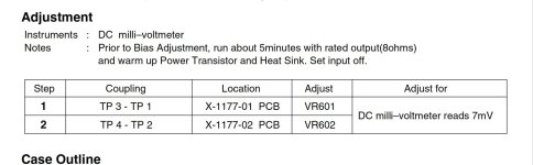
Make sure the amp is warm, and inputs shorted. NOTE: The maintenance manual states "run at rated output in 8ohms for 5min".... I think that's 1kHz into 8ohms resistor, at a power level just before clipping.
You will not be able to hear the difference.... between 3.5 and 7mV
I wouldn't worry at all, though... but that's me....
If you want to find the sweet spot just because you can/want to, adjust the bias for the lowest THD... which for the AB class of amps is usually quite low.
Make sure the amp is warm, and inputs shorted. NOTE: The maintenance manual states "run at rated output in 8ohms for 5min".... I think that's 1kHz into 8ohms resistor, at a power level just before clipping.
You will not be able to hear the difference.... between 3.5 and 7mV
I wouldn't worry at all, though... but that's me....
Normally when you bias something, the meter is hooked up across the resistor, i.e., + lead to one side and - to the other. When you stated "I hooked my meter up to either side of R653" it wasn't clear whether you were measuring one side to ground or not. If so, that could be why you were seeing double the 3.5mV.
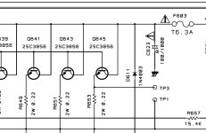
Thanks for the reply. I realize that the partial schematic could have been confusing. If you look to the middle right, you can see TP3 and TP1. They parallel R653, which is what I was measuring across. One side is connected to the emitter of Q645, and the other side is connected to the left output, so theoretically it seems that, if I'm following the bias instructions, I should be trimming to .7mV between those two points..Doesn't this seem correct?
The amp was definitely warmed up. I had it hooked up to an 8r load for a good 20-30 minutes. I did not short the input however. I guess that is what they meant in the testing setup where they said "set input to off"?
Yes, measuring across the resistor is what you should be doing. The wording used in your initial post could have been taken as measuring either side of R653 to ground.
Thanks! It’s just weird that each channel arrived biased at 3.5mV. Makes me wonder if this version, even though it is a rb1080, has a different bias setting. I emailed Rotel so hopefully I’ll get a response. From the schematic it seems to be the same, but it’s hard to tell without completely removing the channel card, which is a pretty major job
Very common for manufacturers to under bias their production amps. Leads to less warranty claims.
- Home
- Amplifiers
- Solid State
- Rotel RB1080 biasing and proper service manual