I got this amp and when i took the cover off the temperature was very high and 2 resistors almost gone :
I adjusted the bias current and dc offset according to the manual and temperature dropped significantly on the transistors.
The area next to the faulty resistor is still very hot (70C) same thing on the resistor itself.
This is not happening on the other pair of resistors (max 32C, right side in photo) but the values are very strange, 1kΩ for the broken one and around 5.7MΩ for the other three.
The manual says that they are 2W 1K...
So i need your help on what to replace, obviously the broken one for start.
I know that these amps running hot but at the moment i guess the heat is because of the faulty resistors.
The amp is working though and sounds great
Is it worth trying to repair?
An externally hosted image should be here but it was not working when we last tested it.
I adjusted the bias current and dc offset according to the manual and temperature dropped significantly on the transistors.
The area next to the faulty resistor is still very hot (70C) same thing on the resistor itself.
This is not happening on the other pair of resistors (max 32C, right side in photo) but the values are very strange, 1kΩ for the broken one and around 5.7MΩ for the other three.
The manual says that they are 2W 1K...
So i need your help on what to replace, obviously the broken one for start.
I know that these amps running hot but at the moment i guess the heat is because of the faulty resistors.
The amp is working though and sounds great
Is it worth trying to repair?
There may be a few people able to help but you need to be more forthcoming with what parts you mean. To get help, post a schematic or a link to the one you have, assuming it's available free on the net. Then specify the resistors with their part numbers.
I found one here: B&W Group North America Service & Support - Service Manuals
Taking a guess, because there aren't that many 1k resistors, you must be referring to R642, 644 - the R channel driver transistor emitter resistors. These do waste a lot of power in this type of output stage so we expect them to get hot but if you read 5.7M, it will just be the circuit resistance, as the resistor will be history.
The hard question is, why? The reason is most likely the associated driver has failed and possibly 1 power transistor too. You can replace the resistor but the shorts will just cause it to run hot and fail again. When unpowered, test the transistors for shorts (both power transistors and the driver) then check the other 3 of opposite polarity as well. You can verify readings from the good channel if in doubt as to what to expect but don't apply power until you locate any such problem short(s) and replace the necessary parts.
Let's see what measurements show first.
Last edited:
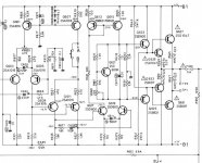
this is the position of the resistors on the schematic The actual use of them I am not familiar with so i cannot comment on why these are getting hot ( topology i have never noticed before ) R641,2,3,4
Some other member may illuminate about this
If you need a schematic i have one
expect to replace them all use better type FP style resistors if the amplifier balances after all these should get warm but not hot ..
Thinking that this amplifier is designed to run hot is wrong warm may be but hot i dont thing so
Kind regards
Sakis
Attachments
Before any repair attempt set up voltage in the correct position Rated voltage in your country should be 240 and not 220
If originally was set up for 220 these few extra volts is enough to disturb bias up to a point and you may wana take a look at it again
Kind regards
Sakis
If originally was set up for 220 these few extra volts is enough to disturb bias up to a point and you may wana take a look at it again
Kind regards
Sakis
Ian seems that we posted in the same minute ..>Do you have any idea on the actual use of this topology ?
good to see you !!
good to see you !!
The second yellow circle under the resistors indicate the area that gets really hot.
Yes Ian, i'm refering to resistors 644 & 642.
With the amp off R644 reads 0.88MΩ and R642 1KΩ.
R641 and R643 6.7MΩ but no hot area on the other channel
Can you guide me exactly which transistors to check?
I have the service manual and keep in mind that the amp is fully operational
Yes Ian, i'm refering to resistors 644 & 642.
With the amp off R644 reads 0.88MΩ and R642 1KΩ.
R641 and R643 6.7MΩ but no hot area on the other channel
Can you guide me exactly which transistors to check?
I have the service manual and keep in mind that the amp is fully operational
Check Q 623, 625, 629, 633, 627, and 631.
I've seen driver transistors get so hot they sort of desoldered themselves from the board over time, resulting in further catastrophe. On a big old Sony amp I was able to pull a couple of them without even desoldering them.
Check the board traces too. It's common for them to be toast.
I've seen driver transistors get so hot they sort of desoldered themselves from the board over time, resulting in further catastrophe. On a big old Sony amp I was able to pull a couple of them without even desoldering them.
Check the board traces too. It's common for them to be toast.
Transistors are ok, but
there are many discoloured soldering points probably caused by high temp as Fast Eddie says.
Also some traces look with different colour.
Whats the solution here?
there are many discoloured soldering points probably caused by high temp as Fast Eddie says.
Also some traces look with different colour.
Whats the solution here?
Needless to say, but an amp of this vintage needs re-cap while you are inside it. Quite a different architecture from the 9 series.
You could always plug it into SPICE and see what what is what. Sometimes, the manufacture does not get it quite right.
You could always plug it into SPICE and see what what is what. Sometimes, the manufacture does not get it quite right.
Use good metal film/metal oxide 2W resistors and make sure theyre far enough away from the PCB to not cause trouble.
Personally, i'd be tempted to modify the circuit - using a single 220-330 ohm resistor to connect the emitters of the driver transistors (Q623/Q625) together, and re-bias.
Personally, i'd be tempted to modify the circuit - using a single 220-330 ohm resistor to connect the emitters of the driver transistors (Q623/Q625) together, and re-bias.
Hi Sakis, I can only with certainty remember seeing this driver arrangement on a similar Rotel amplifier with this overheating driver resistor problem. I recall the resistor type was too close to the PCB, so I fitted new ones with ceramic beads, raised from the board.....Do you have any idea on the actual use of this topology ?....
Douglas Self describes it in his Manual, categorised as EF type III which he says has no popularly imagined class A driver advantage ..... "but is equally as good as type II at reverse-biasing the output bases, and may give even cleaner HF turn-off as the carriers are being swept from the bases by a higher resistance terminated in a higher voltage, approximating constant-current drive ".....
He doesn't say who used it either but I think he really means to say 'pointless'. I suspect this is not a Rotel Japan design and originates from Rotel Europe, back in the day. Look at the topology, layout of the board, heatsink and other stylistic features. Constantly hot components are quite common in UK audio designs of the period so I'll leave your imagination to make the connection. 🙂
Transistors are ok, but
there are many discoloured soldering points probably caused by high temp as Fast Eddie says.
Also some traces look with different colour.
Whats the solution here?
Replace the resistors and check the voltages as shown on the schematic.
I don't understand how it works with an open bias resistor. 😕 I've seen amps that "worked" with an open transistor, but they distorted badly.
How do you know the transistors work? Did you pull them and test them? There will never be a better time.
Recap is a great idea. And as Jaycee says, mount the resistors well away from the board.
It's my experience that many amplifiers use marginal parts; in other words, driver transistors rated 1.5 watts that dissipate 1.5 watts and half watt resistors that dissipate over 0.4 watt.
You can check the board for open traces with the transistors out. Many amplifiers are deemed not worth fixing because the board is too burnt up. You can fix it, but it is up to you whether it's worth it.
On the other hand, my old Nakamichi's circuit board (which is presently apart for service and repair) looks immaculate and brand new. The Sony board is pretty toasty, with parts not even soldered to it anymore 🙁 and traces lifting. I might not even fix it.
I Ohm checked the resistors and i get the same readings on both channels.
I'll resolder the bad points.
I've found these resistors, will they do their trick?
2W 5% Metal Oxide Film Resistors - Variable Values - Pack of - 2, 5 or 10 | eBay
I think there is a part on the pcb that excessive current flows
I'll resolder the bad points.
I've found these resistors, will they do their trick?
2W 5% Metal Oxide Film Resistors - Variable Values - Pack of - 2, 5 or 10 | eBay
I think there is a part on the pcb that excessive current flows
Seems about right if the they are actually quality parts - Ebay is for desperate risk takers when it comes to repairs. Most important is to mount them clear of the PCB, say 8mm min. If they may collapse and short if the solder fails, heatproof sleeving on the leads is a good addition.
Why not try locals like CPC: ROX2SJ1K0 - TE CONNECTIVITY / NEOHM - RESISTOR, 2W, 5%, 1K0 | CPC ?
If the hot spot is not directly under one of those resistors, it may be important but if it's due to the hot resistors, spacing should help, as long as the PCB material itself has not carbonised (blackened) and become conductive.
Here's some name brand, industry standard resistors.
Panasonic ERG-2SJ102V
Invalid Request
Can you get this stuff in your neck of the woods?
Not all metal film resistors are created equal for audio and I haven't done any "blind tests" to offer an objective opinion on metal film vs traditional carbon resistor in this application. Some may claim that changing resistor types will alter the sound. For a bias resistor it will not make as much difference as changing a feedback resistor. Older circuits are usually a little bit slower (not always) and at any rate engineers were forced to design them to work with the parts that were available at the time.
Last edited:
- Status
- Not open for further replies.
- Home
- Amplifiers
- Solid State
- Rotel RA-840BX3 repair?