Hi All,
I've read somewhere that placing a small value capacitor in parallel with the plate resistor or a capacitor in between the plate leg and the cathode leg can roll off the highs, can it be used as an ultrasonic filter so very high frequencies will be blocked?
if so how can I calculate the capacitor value to block frequencies above 100khz?
Thanks
R Ohms
R = 1/(2*pi*fc*C)
C Farads
C = 1/(2*pi*fc*R)
fc (Hz)
fc = 1/(2*pi*R*C)
Low Pass Filter Calculator
R = 1/(2*pi*fc*C)
C Farads
C = 1/(2*pi*fc*R)
fc (Hz)
fc = 1/(2*pi*R*C)
Low Pass Filter Calculator
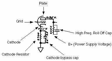
It all depends on where in a tube amplifier the capacitor is installed.
Traditionally, at the "front end", a small ceramic cap of 47 to 100pf plate to ground kept HF oscillations in check.
If the output end was to be "stablised" for whatever reasons, a plate to cathode or plate to plate (PP) kept ringing subdued in the OT.
These of course are old school traditional ways that manufacturers used in their amps.
Naturally, a ton of other ideas will be soon posted, some of worthy use, others containing goofy ideas.
Your mileage may vary.
Naturally, a ton of other ideas will be soon posted, some of worthy use, others containing goofy ideas.
Which one is the most simple and effective?🙂
Which one is the most simple and effective?🙂
Again, it all depends on the design of the amp.
I don't know anything about the amp in question, and cannot speculate on things unknown.
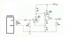
it's a DAC tube output stage
Try putting a 47pf disk cap between the grid and cathode of either section of that tube.
The time constant of any RC circuit is t=RC, so f = 1/(2πRC) is always the
cutoff frequency - but some RC circuits are high pass, so you've got to pick the
right configuration.
cutoff frequency - but some RC circuits are high pass, so you've got to pick the
right configuration.
Correct me If I am wrong, but what you need is a Low Pass Filter.
A single pole filter will only attenuate by 6 dB/Octave.
-3 dB @ 20kHz, about - 9 dB @ 40k.
-1 dB @ 22.05k, - 3dB @ 44.1k
Etc.
You might want to use a multi pole filter, like so many CD players use.
A single capacitor is not a multi-pole filter, except in certain more complex circuits.
A single pole filter will only attenuate by 6 dB/Octave.
-3 dB @ 20kHz, about - 9 dB @ 40k.
-1 dB @ 22.05k, - 3dB @ 44.1k
Etc.
You might want to use a multi pole filter, like so many CD players use.
A single capacitor is not a multi-pole filter, except in certain more complex circuits.
If you refer to *this* image (half a dozen in that link),Thanks
In your link the capacitor is not in paralell with the resistor, it's grounded on one side.
In this link it's shows that the capacitor is in paralell with the resistor, should I still use your formula or a different calculation should be made?
one end of the capacitor is tied to tube plate, the other is *always* grounded 😱, either straight to ground or to the +V node, which for all purposes IS audio ground, since it´s decoupled to it.
Only extra detail to consider is that the "R" used in the formula is the generator source impedance, which in this case would be the load resistor (220k in the example) in parallel with tube internal impedance,conventionally around 68k , so combined source impedance to use in calculation will be around 40k.
The design site linked above considers "pure" resistance of course, driven by a perfect generator.
Last edited:
Hi All,
I've read somewhere that placing a small value capacitor in parallel with the plate resistor or a capacitor in between the plate leg and the cathode leg can roll off the highs, can it be used as an ultrasonic filter so very high frequencies will be blocked?
if so how can I calculate the capacitor value to block frequencies above 100khz?
Thanks
(Sample)RC Low-pass Filter Design Tool - Result -
Consider 10nF across the 150R (-6dB at ~105kHz), SMD type between grid pin and grounded centre spigot on socket would have zero lead length, which is desirable at HF.
HK
Consider 10nF across the 150R (-6dB at ~105kHz), SMD type between grid pin and grounded centre spigot on socket would have zero lead length, which is desirable at HF.
HK
Which option is better, next to the 150r resistor (DAC pcb) or directly on the tube Grid and GND?
Thanks
Connecting a cap from a control grid to ground will ruin the effect of a grid stopper resistor action.
And, if you do not have a grid stopper resistor, you may need one.
And, if you do not have a grid stopper resistor, you may need one.
What resistor value should I use that won’t affect the signal level?
Is there any formula for that?
Thanks
Is there any formula for that?
Thanks
Formula for a value of grid stopper is not so easy, in practice there are many variables, you can reduce tendancy for oscillations with component layout.
Search forums for tips on this and you will find lots of helpful information.
Before resorting to grid stopper, try ferrite bead over socket pin and SMD capacitor from top of socket pin to grounded centre spigot, zero lead length.
HK
Search forums for tips on this and you will find lots of helpful information.
Before resorting to grid stopper, try ferrite bead over socket pin and SMD capacitor from top of socket pin to grounded centre spigot, zero lead length.
HK
Last edited:
- Home
- Amplifiers
- Tubes / Valves
- Roll off highs using a capacitor