Hello,
today an old Rockford Punch 4040 dsm with power supply blown and no sound of one output.
1) The power supply (repaired): thanks to Perry Babin schematics (from an old post); some FETS burned and some part of the board became conductive !!!
2) The output stage: channel RIGHT FRONT with one of the two BUZ 11 without gate signal.
Signal cames from pin 24 of another board (HB101 / WP-0040C), probably broken (all input signals are ok, some SMD transistor are hot, ...), but i don't found any information about it.
Do you have any information (or better a schematic) of this little circuit ?
Thanks
Giovanni
Hy Perry,
another little question, probably because i don't understand completly the circuit logic ...
To solve first failure, i replaced Q15 and the 33 ohm emitter resistence. After that Q15 output signal (pin 24) is low and I don't understand why.
I try to explain with some waveforms after Q14 replacement.
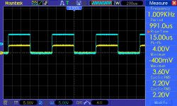
PIC121_3 is taken from pin 24 (yellow) and pin 16 (blue) of another driver module perfectly working.
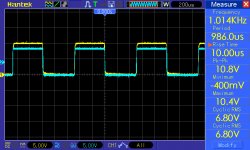
PIC121_2 is taken from pin24 (yellow) and pin 16 (blue) of this board.
PIC 121_4 is taken from Q14 collector (yellow) and Q13 collector (blue).
PIC 121_5 is taken from Q14 emitter (yellow) and Q13 emitter (blue).
Could you help me with some other ideas ?
Thanks
Giovanni
another little question, probably because i don't understand completly the circuit logic ...
To solve first failure, i replaced Q15 and the 33 ohm emitter resistence. After that Q15 output signal (pin 24) is low and I don't understand why.
I try to explain with some waveforms after Q14 replacement.
PIC121_3 is taken from pin 24 (yellow) and pin 16 (blue) of another driver module perfectly working.
PIC121_2 is taken from pin24 (yellow) and pin 16 (blue) of this board.
PIC 121_4 is taken from Q14 collector (yellow) and Q13 collector (blue).
PIC 121_5 is taken from Q14 emitter (yellow) and Q13 emitter (blue).
Could you help me with some other ideas ?
Thanks
Giovanni