I am working on a Rockford Fosgate T1000.1BD that had a blown power supply. It was ugly. I replaced the power supply mosfets and checked all of the SMD components in the power supply section. I didn’t find any other issues in the power supply. The power supply has four other components mounted to the heat sink that tested good that I did not replace. They are a pair of LM317T and a pair of U1620G.
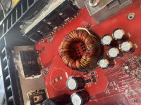
The output section had some issues as well. Two swollen rail caps that I replaced and four dead output mosfets Q207,Q208,Q209,Q210. The other set of four output mosfets were fine.
I connected the positive and negative with no remote power and the amp pulls high current. I connected it again with current limited supply and found that the back corner of the power supply mosfets were getting hot. I don’t see any obvious reverse protection diodes. Does anyone know if this amp has any reverse protection and if so, where it might be located.
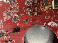
While I was looking the board over closely I also noticed a cracked diode (D11)and two really cooked SMD resistors (R58 and R32) next to the fan in the center of the board close to the output section that I hadn’t seen before connecting the power back up. Does anyone know the value of these resistors? A schematic?
Thanks,
David
The output section had some issues as well. Two swollen rail caps that I replaced and four dead output mosfets Q207,Q208,Q209,Q210. The other set of four output mosfets were fine.
I connected the positive and negative with no remote power and the amp pulls high current. I connected it again with current limited supply and found that the back corner of the power supply mosfets were getting hot. I don’t see any obvious reverse protection diodes. Does anyone know if this amp has any reverse protection and if so, where it might be located.
While I was looking the board over closely I also noticed a cracked diode (D11)and two really cooked SMD resistors (R58 and R32) next to the fan in the center of the board close to the output section that I hadn’t seen before connecting the power back up. Does anyone know the value of these resistors? A schematic?
Thanks,
David
Attachments
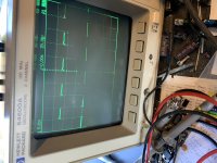
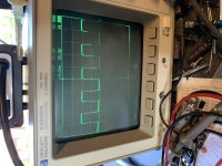
If you connect only remote and ground (no B+), You can look at the drive signals for the PS FETs without high current draw.
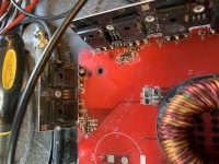
The board is out of the heatsink. Ground and remote power connected and no B+.
Ok. I have good drive coming out of U3 IC both outputs. I check the drive at the gates of the power supply mosfets and there was none. I discovered the the pnp drivers of darlington pairs of Q1,2,3,4 were shorted. I replaced the pnp and npn drivers of those darlington pairs with 1A and 2A SMD drivers that I had in stock. 1A is a mmbta42 and 2A is a mmbta92.
I now have drive on the gates of all of my power supply mosfets except for two. The power supply mosfets are 75344G. The two that don’t have drive are the ones that were heating up before. They are in back corner of the board (Q8 and Q5). Q6,7,11,9 all have good drive.
When I connect power B+ with current limited the amp tries to draw high current(6amps). When I probe the gate of Q8 that doesn’t have drive with my probe grounded to the negative power terminal I can see the drive build on the gate and then the blue light comes on for the amp and I can probe the mosfets in the output section and I see really good drive on them and the amp draw for the amplifier drops down to about 2 amps from 6 amps and I can watch the drive slowly fade away and the current draw goes back up to 6 amps. It seems like the cat of probing the gate of Q8 offers a path to ground through my probe and the amp boots up. What do you think could be the issue?
David
Attachments
Yes I did. Thank you Perry. I found the break. It was a tough one to ferret out. The trace was broken underneath the mask of the PCB board. It was the tiny trace that ran along the back edge of the board from gate to gate.
I found it by connecting the black probe of my meter to the ground terminal and probed around until I found were I lost my path to ground. When I found it I installed a jumper wire.
I just finished testing the amp. Works great. Pulls just under 3 amps at idle. Does that sound about normal for this amp?
Thanks for your help,
David
- Status
- Not open for further replies.
- Home
- General Interest
- Car Audio
- Rockford Fosgate T1000.1BD pulling High Current