Hello everyone.
I recieved a punch 500x 4 channel amp in for repair. The board number is PC-3084-C.
The amp was dead and would not power up. I rebuilt the power supply completely. I replaced all 4 IRF3205 p/s fets, and replaced their gate drivers with new 47 ohm resistors. I also replaced the 4 driver transistors next to the PWM chip. I hooked up power and nothing.
The amp has no rail voltage, and the regulators are all at 0.000 vdc. I have no voltage on any of the op-amps either. I do not get any rail voltage on the output fets either.
I tested the LM339 and the TL494C and here is what I found:
LM339
pin 1: 0.008 vdc
pin 2: 6.05 vdc
pin 3: 13.20 vdc
pin 4: 0.166 vdc
pin 5: 2.579 vdc
pin 6: 4.98 vdc
pin 7: 6.49 vdc
pin 8: 4.36 vdc
pin 9: 4.98 vdc
pin10: 4.98 vdc
pin11: 8.24 vdc
pin12: 0.000 vdc
pin13: 6.06 vdc
pin14: 6.06 vdc
TL494C
pin 1: 0.021 vdc
pin 2: 4.69 vdc
pin 3: 0.063 vdc
pin 4: 0.099 vdc
pin 5: 1.520 vdc
pin 6: 3.400 vdc
pin 7: 0.001 vdc
pin 8: 13.21 vdc
pin 9: 5.13 vdc
pin10: 5.13 vdc
pin11: 13.21 vdc
pin12: 13.21 vdc
pin13: 4.98 vdc
pin14: 0.012 vdc
pin15: 4.98 vdc
pin16: 0.001 vdc
When testing pin 4 on the TL494C as I touch the probe to pin 4 it makes a squeelching noise somewhere in the amp. Sounds like static or the squeelch on a CB radio.
None of the output fets seem to be shorted, and I have not found any open traces. The led light does not light up, but you can see a slight draw on the power supply and hear a small click when the remote voltage is applied.
Thoughts anyone????
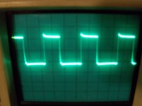
The power supply IC is producing output. You should have drive pulses on the gates of the power supply FETs. Compare the signal on pins 9 and 10 to the signal on the gate legs of the FETs. Set the scope to 5v/div and 10ms to start.
The power supply IC is producing output. You should have drive pulses on the gates of the power supply FETs. Compare the signal on pins 9 and 10 to the signal on the gate legs of the FETs. Set the scope to 5v/div and 10ms to start.
Wondering if you meant 10us instead of 10ms?
With 5v/div and 10us I get a nice square wave form on the gate legs of the p/s supply fets. Cant get anything on pins 9 and 10. If I use 10ms the scope will trigger on the gate leg of the p/s fets but it wont lock onto a wave form. Still same result on pins 9 and 10, nothing......
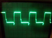
OK I got a signal from pins 9 and 10 very nice square waveform. Compared to the gate legs of the p/s fets the signal is slighlty different. The gate leg signal slightly deflects below the baseline. It is not quite as square as the signal from pins 9 and 10. First pic is pin 9 and 10, second pic is gate leg of p/s fets.
Scope settings are 5v/div 10us
Scope settings are 5v/div 10us
Attachments
Upon very close inspection of the transformer I found one leg broken from the solder joint and another completely broken in half. I noticed some black marks around one of the solder joints where it had been arcing. I was able to resolder the one leg as there was enough wire left. The other leg was to short so I had to clip another piece of wire from another parts toroid and solder it to the broken leg then to the board. I hooked up power and the amp powers up fine. I will test the audio and post my result.
Just wondering how much load is on the leg and if the solder will hold? I overlapped them about 1/8" and soldered them together that way. Got adequate flux and a nice clean solder joint, dont think it could be any better at least to my ability. I would think it would hold up fine.
Thoughts on the solder joint???
Yes. It should have been 10us.
1/8" of overlap is not much but I'd be more concerned about its ability to withstand vibration. To determine if there's a problem due to resistance, drive the amp hard to see if that point gets warm/hot.
1/8" of overlap is not much but I'd be more concerned about its ability to withstand vibration. To determine if there's a problem due to resistance, drive the amp hard to see if that point gets warm/hot.
Ok I resoldered it with a new piece and overlapped about 1/4" this time. I just made a bone head mistake. I forgot to set the bias before testing for sound. I played music at a low volume with a speaker bridged on the front and rear. The amp started drawing alot of current and some components got real hot on the board and were smoking. I shut the amp off. I restarted it and tried to set bias and it is not working right. The front channels start pulling current almost right after you start turn the pot. The rear channels just start to draw current and then jump way up and I have to turn the pot down. Was this caused because of me playing the sound without the bias set or could this be an existing problem due to the legs on the transformer being broken? Could this problem have caused the legs to overheat and break on the transformer originally?
This didn't cause the transformer legs to break.
Did you replace the outputs in the front channels or in the rear channels?
Are they from the same batch of parts?
Did you have the outputs clamped down when the biasing did as you described after something smoked?
Did you replace the outputs in the front channels or in the rear channels?
Are they from the same batch of parts?
Did you have the outputs clamped down when the biasing did as you described after something smoked?
I didnt replace any outputs, and yes the amp was in the sink when I was settinng the bias. I was wondering since I tried to play sound without the bias set if that could have messed up some components? I forgot to reset before I tested for sound, never have done this before I am really mad at myself. I now have 30vdc on the bridging terminals of the rear channels. I dont have any dc on the front channels.
Playing it without having the bias set won't cause a problem. If the bias was set too high, the outputs would have overheated with/without playing it.
I replaced Q405 and Q305 which are 2AM and that got rid of the dc on the bridging terminals of the rear channels. Is there something else I should be checking? Maybe I have some bad smd resistors?
I dont have time to check it something is getting hot and smoking but I cant tell what. Maybe it is the flux around the components I just changed. As these components get hot the dc returns on the bridging terminals.
Both of the IRF9540 in the rear channels have like -2.250 from gate to source and whatever is getting hot increases that voltage as it gets hotter. The IRF540's from the rear have 0.000 vdc from gate to source.
Both of the IRF9540 in the rear channels have like -2.250 from gate to source and whatever is getting hot increases that voltage as it gets hotter. The IRF540's from the rear have 0.000 vdc from gate to source.
Do you have excessive current flow through both rear channels? Measure the DC voltage across the 0.1 ohm source resistors if you don't know if it's one or both channels.
Yes it is through both channels. Something starts smoking on both channels. It has to be something close to the 2A's I changed because its got to be getting the flux residue hot to smoke like that.
It seems the heat is coming from R423 and R452 on one channel, and R323 and R352 from the other. It takes a second then the amp current draw goes up just a little on my power supply amp meter, then the components start heating making the dc return.
Does this amp use the BUZ outputs?
If so, did you check to see if they were shorted gate to source? These transistors commonly short that way instead of drain to source.
If so, did you check to see if they were shorted gate to source? These transistors commonly short that way instead of drain to source.
No it uses the IRF540 and IRF9540. I would probably have to remove them from the circuit to test for short or leakage?
R323 and R423 are directly connected to the emitters of the 2A's I replaced. I have 100's of IRF540 and IRF9540's I could change them out to eliminate them as a fault. The channels were producing audio until the dc came. Maybe they shorted?
I could clip the legs and turn on the amp and see if the heating goes away in the components???
Last edited:
I replaced the output fets in the rear channels. I powered up the amp and all seems to be well. I let it idle for 15 min with no heating or smoking. I no longer have voltage from gate to source either. I am going to replace the front channels output fets as well. When I get that done I will set the bias and try for audio again.
I will post my results later.......need sleep.
I will post my results later.......need sleep.
- Status
- Not open for further replies.
- Home
- General Interest
- Car Audio
- Rockford Fosgate Punch 500x 4 channel