I am the owner of a RF Punch 200 DSM.
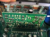
Unfortunately, RF Punch 200 DSM has a defect; on the driver module - Punch DSM N-Ch Driver Module PC-0040B 6-T-93(please see picture attached) - there is one burnt resistor (on both channels) and I can't identify it's value.
Can anyone tell me, please, which is that value and if it is a known reason which can lead to this?
Attachments
driver board
The driver boards are available from out of warranty service in north carolina. I think the name is Freemans Car Stereo. Call rockford for info. 480-967-3565 I think. they are about $35 each. If you cannot fix it I can have it serviced here in Az.
The driver boards are available from out of warranty service in north carolina. I think the name is Freemans Car Stereo. Call rockford for info. 480-967-3565 I think. they are about $35 each. If you cannot fix it I can have it serviced here in Az.
is it one driver board per channel? I thought it was. In that case, you an read the resistor value off of the good channel. Be sure to test the surface mount transistors to make sure they survived the incident. I would also check the outputs to make sure they aren't hsorted gate-source or some other failure that would take out the driver module again after you fix it.
Boxcustom
I am from Romania, Europa.
Thanks anyway.
Dr. Photon
There is indeed a driver module for each channel, but the problem exists on both of them.
The transistors from the final module were checked and were ok.
The transistors from the driver module, measured with a multimeter, seemed to be ok.
There is a transistor; the SMD code is 8A (maybe a so-called digital
transistor, with resistors within, type MUN 2211 or a zenner diode 3V3, type MMBZ5226B). In the base of this transistor ( the pin no. 2 of the SOT23 capsule) you can find the resistor which is burnt. The other end of this resistor goes in the collector of a transistor with the code G1.
Thanks
It's likely a 68K ohm.
http://www.bcae1.com/temp/punchdriverold1.swf
http://www.bcae1.com/temp/punchdriverold2.swf
These are flash files so you can right-click and zoom in on the image. Use your mouse to move the image to the desired area.
The burned resistor on one of the pictures above is a 33ohm.
http://www.bcae1.com/temp/punchdriverold1.swf
http://www.bcae1.com/temp/punchdriverold2.swf
These are flash files so you can right-click and zoom in on the image. Use your mouse to move the image to the desired area.
The burned resistor on one of the pictures above is a 33ohm.
Thank You for your help, Perry Babin; the first picture seem to be identically with what I have.
Anyway, during this week I'll check and change the resistors, I'll be back with the result...
Anyway, during this week I'll check and change the resistors, I'll be back with the result...
The 68k burnt resistors were replaced. Now the amplifier functions, but the following thing happens:
with a signal generator on the input (level of the signal choosen to be right before limiting on the output; frequencies of 400 Hz or 1kHz), without connecting any speaker to the output, the input frequency signal can be actually heard (on a smaller level).
the input signal can also be obsserved on the power voltage (both + and - ) with an amplitude of 250mV p-p.
If the amp has no DC on the output terminals (check with a multimeter on DC volts) and the amp is not drawing more than ~1.5 amps at idle, I would connect a speaker to the amp and play some audio (music) through it.
If the scope, the power supply and the signal generator are not grounded together, you may see the signal on the power connections. In the US, virtually all test equipment is grounded through the mains connection so the grounds are made automatically. I don't know if you have the same type of mains setup where you are.
If the scope, the power supply and the signal generator are not grounded together, you may see the signal on the power connections. In the US, virtually all test equipment is grounded through the mains connection so the grounds are made automatically. I don't know if you have the same type of mains setup where you are.
- Status
- Not open for further replies.
- Home
- General Interest
- Car Audio
- rockford fosgate punch 200DSM - Help needed