I am restoring a rockford fosgate power 650 that had one blown channel what appeared. I replaced both lm833 op amps and all the audio output for all 4 channels. I tested all the powersupply fets and rectifiers to be good. Cleaned the solder pads, bent the leads, and reinstalled them. I left the fuses out of the channels to just to see if amp powers up fine. When power is applied it pulls my 52 amp powersupply down to 2v like it sees a direct short. I remove power and check for voltage on caps and pwsupply fets and there is source voltage on powersupply fets. I did notice that there is no voltage across the larger capacitor and rectifiers on the right side of amp and powersupply voltage on the left side.
Also if anyone has a schematic for the power 650 green ckt board version this would be helpful.
Also if anyone has a schematic for the power 650 green ckt board version this would be helpful.
I think I have figured out the problem, when the amp came in for restoration and upgrades it was missing the outputs towards the powersupply. So I rebuilt the amp mimicking the opposite of the board and just now realized my error. I installed a mje3055 instead of using a mje2955t. I will keep you guys posted of the restoration once I get the replacement chip.
Perry,
Thank you for the recommendation on the equivalent transistor and yes I had some 2n6491 chips in stock. My mistake on the powersupply, it does not have FETS. It uses the D44Vh10 and D45vh7 transistors.
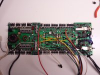
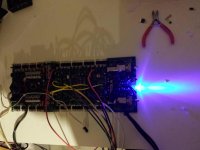
Installed the 2n6491 and BAM I was up and running. I also removed that old red LED and replaced it with a super bright blue LED with a 3.2 v @ 20mA. Man what a difference!!! Below is a pic of the circuit board now and one with blue LED ON.
Thank you for the recommendation on the equivalent transistor and yes I had some 2n6491 chips in stock. My mistake on the powersupply, it does not have FETS. It uses the D44Vh10 and D45vh7 transistors.
Installed the 2n6491 and BAM I was up and running. I also removed that old red LED and replaced it with a super bright blue LED with a 3.2 v @ 20mA. Man what a difference!!! Below is a pic of the circuit board now and one with blue LED ON.
Attachments
Perry I started working on this amp again and applied an audio signal for testing the output and had no audio out. I did find a bad zener in front of the 2n6491 I installed. I started checking g this area because I had no -17 on pin 4 of the lm833n chips. After replacing the zener I noticed that a diode beside the a06 transistor and the zener. Someone took the diode to the large cap then to the pin hole and added a 2k resistor from the diode to the trace. I didn't understand why they did so I installed the diode like factory and removed the resistor. I have the -17 at the op amps now but when Install the fuses they pop. I used irf540n and irf9540n and these worked great last. My question is why did they added the 2k resistor?
The mods you made may have changed the voltage used for biasing and the bias may need to be reset. Set the bias pots fully counter-clockwise and see if that helps.
Q619 is one of two transistors that switch the regulated voltage to the op-amps in the power amp circuit. If the positive and negative voltages are delayed for a few seconds for those op-amps, it would appear that it's working properly.
Q619 is one of two transistors that switch the regulated voltage to the op-amps in the power amp circuit. If the positive and negative voltages are delayed for a few seconds for those op-amps, it would appear that it's working properly.
I adjusted the pots fully counterclockwise prior to powering the amp up. They still pop but it usually only 1 of the 3 out of 6 for each channel. I didn't install that mod I was putt the diode to the original position and orientation. But I think it was installed prior by another tech maybe due. To original problem that couldn't be found.
The 'mod' I was referring to was whatever you did to get it to where it is now.
If you power the amp through a current limiter, will the fuses hold long enough to see what each channel is doing (only fuses in one channel at a time)?
If you power the amp through a current limiter, will the fuses hold long enough to see what each channel is doing (only fuses in one channel at a time)?
Perry,
I found a set of irf540 and 9540. I removed the N version because they would blow with bias fully ccw as soon as I put a 60hz test tone to it. I installed the new chips and I was able to see a noisy audio signal until I adjusted the bias a tiny bit then the waveform was perfect. This lasted about 5 minutes with audio and gain all the way down. The fets got and one shorted. Keep in mind this is out of the heatsink. What I did notice is that the 3055 and 2n6491 are super hot. Don't remember if this is normal. I do have 19v instead of 17.5 on the 3055. I have to order some more fets now. With no audio and moving the bias from fully ccw until the current starts to draw the pot setting is about 75 ohms. Does the 19v being higher affect the position of the bias on the fets?
I found a set of irf540 and 9540. I removed the N version because they would blow with bias fully ccw as soon as I put a 60hz test tone to it. I installed the new chips and I was able to see a noisy audio signal until I adjusted the bias a tiny bit then the waveform was perfect. This lasted about 5 minutes with audio and gain all the way down. The fets got and one shorted. Keep in mind this is out of the heatsink. What I did notice is that the 3055 and 2n6491 are super hot. Don't remember if this is normal. I do have 19v instead of 17.5 on the 3055. I have to order some more fets now. With no audio and moving the bias from fully ccw until the current starts to draw the pot setting is about 75 ohms. Does the 19v being higher affect the position of the bias on the fets?
Without having the FETs clamped, I would have expected them to fail in just a minute or so with the bias set.
The regulators are going to get hot. They're dropping 25-30v. In some amps, the regulators will fail almost instantaneously if not clamped down.
With the string of 1N4148 diodes, I don't think that the difference in regulated voltage will cause the bias to vary significantly. I could be wrong.
I've had at least one of these amps where the bias control didn't have enough range and I had to change a resistor value (don't remember which one). The newer transistors probably have a lower threshold voltage.
Perry,
I changed the 470 ohm resistor in series with 1k pot to a 270ohm. This allowed to adjust the pot to about 25% before the current meter needle started to move. This is with using Sanken irf540&9540 fets. At this point curiosity has me thinking to lower the value to 150 ohm and try it with the irf540n&9540n. This seems to work. I was able to adjust the pot to about 280 ohms when the current meter started to move.
I changed the 470 ohm resistor in series with 1k pot to a 270ohm. This allowed to adjust the pot to about 25% before the current meter needle started to move. This is with using Sanken irf540&9540 fets. At this point curiosity has me thinking to lower the value to 150 ohm and try it with the irf540n&9540n. This seems to work. I was able to adjust the pot to about 280 ohms when the current meter started to move.
The N versions caused a lot of problems in other Rockford amps. You can try them again but if the amp does strange things, go back to the non-N version. I had an alpine that used the N-version originally and they would not work. I had to use the non-N version.
Correction.... I applied some audio to the channel that I adjusted the bias that has if9540n&540n fets and they blow immediately. The version that doesn't have the N seen to hold up
Yeah its kinda weird....I have used the N version on the last 3 power 650 builds no problems. The bias. Adjustments were all different positions too.
When I first started using the N-version, it was in several 500a2 or 500.2, don't remember. I had 3 in a row with various problems. The worst would trip the protection circuit immediately. The others had less serious problems but still didn't work perfectly. Changed to the non-N and that solved all problems.
- Status
- Not open for further replies.
- Home
- General Interest
- Car Audio
- Rockford Fosgate Power 650