Hello,

This amp Has blowd up, fixed and now again does not work.
Amp side seems ok, maybe some measurement differences shown on fets.
Regulator side larger difference on quick measurement between 2 lm337´s.
Power supply there is 2 shorted per side.
Is it good thing at this point change all the parts hugging heatsink?

rca´s ripped too, i need schematics cause otherside of the board has things going on.
Does anyone has picture of new rca rockford used these amps, ground pin is rather interesting, maybe i have to use some jumpers
This amp Has blowd up, fixed and now again does not work.
Amp side seems ok, maybe some measurement differences shown on fets.
Regulator side larger difference on quick measurement between 2 lm337´s.
Power supply there is 2 shorted per side.
Is it good thing at this point change all the parts hugging heatsink?
rca´s ripped too, i need schematics cause otherside of the board has things going on.
Does anyone has picture of new rca rockford used these amps, ground pin is rather interesting, maybe i have to use some jumpers
Thanks again Perry.
I thought blown parts were D16-D19.
Everything seems to be in order, was it your first tip to check rca ground.
Well, might be only problem with this one, i didn´t power this one up yet cause my amp meter is still on the way
I thought blown parts were D16-D19.
Everything seems to be in order, was it your first tip to check rca ground.
Well, might be only problem with this one, i didn´t power this one up yet cause my amp meter is still on the way
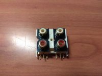
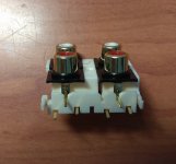
yes, mines does not have ground pins. your part has soldered pins.
there´s no soldering on original part, maybe has been just spring loaded connection
last person who soldered rca part ripped board.
i think i´ll be just fine fixing rca part
there´s no soldering on original part, maybe has been just spring loaded connection
last person who soldered rca part ripped board.
i think i´ll be just fine fixing rca part
The RCA connections are all soldered. There are no spring loaded connections. All RCAs have ground pins soldered into the board.

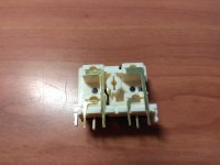
what is so strange for you? the 2 GND legs are ripped away. both of them was there place but after long time and use of the rca cable connectors they ripped out.
you can take leg of resistor or diode and solder it to the point it ripped and you have "brand new RCA socket"
you can take leg of resistor or diode and solder it to the point it ripped and you have "brand new RCA socket"
Yeah have to fix thru-holes cause connections between sides are gone and after i solder that pin there is atleast trace left from soldering
You can jump the shield grounds on the bottom of the board. Do the other two traces go anywhere on the top of the board?
I wouldn't worry about 40mv of DC. Some consider the limit to be about 25mv.
If you want to chase it down, the differential amplifier transistors are where I'd start. You need to use transistors from the same batch and you may have to try multiple pairs to get the lowest offset (or whatever you consider acceptable).
If you want to chase it down, the differential amplifier transistors are where I'd start. You need to use transistors from the same batch and you may have to try multiple pairs to get the lowest offset (or whatever you consider acceptable).
I sure want to take it lower. ummm... Q305-309?
i have to order some capacitors from mouser, could take these at same time.
Another question, under the fets are 2 aluminium slides, these suppost to isolate fets from ground, right?
i have to order some capacitors from mouser, could take these at same time.
Another question, under the fets are 2 aluminium slides, these suppost to isolate fets from ground, right?
Last edited:
That area on the board is so tight with my tools i dont wanna touch.
i was told rather changing those transistors maybe change resistor size Rx83or Rx69, what do you think about that?
those resistors are on same crowded area
Today amp was playing 3ohm mono full range over 4 hours, bias set to 2mV, heatsink barely 30celcius
i was told rather changing those transistors maybe change resistor size Rx83or Rx69, what do you think about that?
those resistors are on same crowded area
Today amp was playing 3ohm mono full range over 4 hours, bias set to 2mV, heatsink barely 30celcius
Last edited:
Okay,
Started to work with channel which had 40mV dc, took Q425 and Q424 off with heatgun.
crowded area so tried to be careful with heat.
After changing them turned amp on, saw 16mv DC keeping probes on, saw high numbers, there was cold soldering on Q424 slightly touching it it went down to 16mV again.
fixed soldering, after that amp has taken much current, it rises over 40amps.
changed new D430 and Q424, Q425 and no help.
Taking Q424 Q425 off board amp draws 0,9amps, so other channel works.
with those two off board there is 92volts ac on speaker output.
What did i do wrong, with heatgun and tweezers it looked like easy job
Last edited:
high AC went away by itself, there was buzzing sound heard when AC was high, there might be cold solder somewhere.
sure i have to compare some measurements from working channel
buzzing sound was heard too when amp was working for many hours, i thought it was transformer buzzing
sure i have to compare some measurements from working channel
buzzing sound was heard too when amp was working for many hours, i thought it was transformer buzzing
- Status
- Not open for further replies.
- Home
- General Interest
- Car Audio
- Rockford Fosgate 250m2, badly beaten up