What do you think of this schematics
http://focus.ti.com/docs/prod/folders/print/opa2111.html
figure 8 page 10
lowering the output resistor and inceasing its capacitor?
Inceasing the gain by lowering the resistor to ground,how much would that change to curve?
http://focus.ti.com/docs/prod/folders/print/opa2111.html
figure 8 page 10
lowering the output resistor and inceasing its capacitor?
Inceasing the gain by lowering the resistor to ground,how much would that change to curve?
This output POLE is for RF elimination....
They put the pole close to 50kHz....
From a real "quick and dirty" look at the RIAA stage...
The low frequency Gain is roughly 46dB....
With Pole# 1 at 47.56Hz...
MidBand Gain shows up at 28dB...
Your ZERO (Turn-over frequency) is 505Hz...
And POLE#2 somehwere around 1.75 Hz....
I would need to spend time to calculate these things with more precision...
They choose these resistor values based on setting the Capacitors first to easily obtianable values, such like .01uF ...
You can lower the 365 ohm resistor and increase the Cap to keep the RC product fairly constant...personally I would remove this filtering unless you have RF issues...
Unless you are refering to 100K and 1uF section....?
That would not really affect the Gain or curve much unless you really wnet down very low and loaded down the output...
If you wanted to reduce gain of the Op-Amp you could reduce the 365 ohm resistor on the left of schematic but then you would run into the floor before you got out to 20Khz....... I would use a 100K pot in place of the 100K resistor to alter the output gain without disturbing the op-amp and network..
Chris
Thanks cerrem
The capacitor values are what interest me. I have different types of .01uf caps. This wills me a chance to switch out caps.
The capacitor values are what interest me. I have different types of .01uf caps. This wills me a chance to switch out caps.
I left the filtering out. I’m burning it in now.😀cerrem said:
You can lower the 365 ohm resistor and increase the Cap to keep the RC product fairly constant...personally I would remove this filtering unless you have RF issues.
Chris
It not killing my ears, I guess it has potential. The only thing is the gain seems kinda low, later I think I will add a compound op amp with some gain.
I have not used polystyrene caps before; I didn’t know what to expect sound wise. How the sound of these caps would be characterized?
BTW I’m using the OPA2111
Looks like a good op-amp, but the slew rate is only 2 nominal.
A SR of about 10-13 is usually typical, as I recall.
The 365 ohm is a filter, but it may also have the function of a resistive load so the amp doesn't slew.
Just a thought/guess. If you have removed the filters on the output you may want to have about 10 ohms there.
Seems to me that all the output filters could be eliminated. A precision op-amp like that shouldn't have enough offset to require a blocking cap. Been awhile since I built a phono stage.
Also, concerning the gain at 1kHz. I don't know why they depict it like that. The actual situation (if I remember correctly) is that there is unity gain at 20KHZ and maximum boost of gain=1000 at the lowest freq, I suppose that would be 20Hz.
As a general rule I am very cautious about reproducing a schematic exactly. There is often something that really doesn't make a lot of sense and the output filters could be one of them. Or, they could be the appendages for the new RIAA revised curve that was being put into play just as the CD came online. It was (or is) a revision to the low end to get rid of rumble. If I had the time I would dig it out of some books.
Please keep in mind that I am not trying to steer you in any direction, only bringing up what may be points of analysis. Mark
hailteflon said:
Just a thought/guess. If you have removed the filters on the output you may want to have about 10 ohms there.
I'll try it today,up to this point I havent had any problems.
Before the output,there is about 200mv dc on each output.hailteflon said:
Seems to me that all the output filters could be eliminated. A precision op-amp like that shouldn't have enough offset to require a blocking cap. Been awhile since I built a phono stage.
Your opinions are valued.🙂hailteflon said:
Please keep in mind that I am not trying to steer you in any direction, only bringing up what may be points of analysis. Mark
about 200mv dc on each output
Now I remember, the high DC gain causes the output offset. Time to review op amp theory.
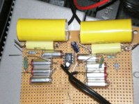
Ive been listening for two days now. One thing I notice is the bass didnt sound quite right. I added a 5uf cap to the output,the bass sounds better now🙂. The next problem to deal with is,the low gain. The volume control has to been bewteen 2 and 3 O'clock for a moderate level.
Attachments
I'm going to go out of bounds here with some criticism.
You are not going to get anywhere near the potential out of your op-amp with that board. Wires all over the place. No filtering on the power supply pins.
You need to study wiring technique. Standard op-amp tutorials from major manuf. have essential information, but it takes a while to go through them over and over until the theory sinks in.
As an instant remedy for your board's potential for oscillations: strap a 1000pf ceramic (preferably NPO) across the V+ and V- power supply terminals underneath the board. This will greatly stabilize oscillations.
You have chosen a hi-performance op-amp. Like a high-performance automobile engine, they require more understanding to make them operate properly.
Criticism is OKhailteflon said:I'm going to go out of bounds here with some criticism.
This is a uncased test board. The leads from the resistors and caps maybe cut. There are 10uf caps at the pins. Take another look at the picturehailteflon said:
You are not going to get anywhere near the potential out of your op-amp with that board. Wires all over the place. No filtering on the power supply pins.
"Wires all over the place" ???
This is far from being my first project.hailteflon said:
You need to study wiring technique. Standard op-amp tutorials from major manuf. have essential information, but it takes a while to go through them over and over until the theory sinks in.
Remember this is just a test board. If I can get it to work to me liking then I will built is with different chips,clean it up and case it.hailteflon said:
You have chosen a hi-performance op-amp. Like a high-performance automobile engine, they require more understanding to make them operate properly.
I have no oscillation problem. .1uf ceramic are already under the board but thanks for the suggestionhailteflon said:
As an instant remedy for your board's potential for oscillations: strap a 1000pf ceramic (preferably NPO) across the V+ and V- power supply terminals underneath the board. This will greatly stabilize oscillations.
Attachments
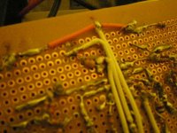
hailteflon said:Wires all over the place.
http://www.diyaudio.com/forums/attachment.php?s=&postid=624279&stamp=1114047068
😀
hailteflon said:electronics, or modern art?
electronics: modern art: electronics😉
I was listening for about 3 day. So far I only used the shure S10 and ortofan pro10 cartridges. I think I paid $42 for both cartridges, so the cartridges are on the cheap side. I don’t know if it is the capacitors or the design but I like this amp better than the VSPS. For one thing everything seems clean and clear.
The next thing is to work on a good power supply, right now I’m using 9volt batteries (last neatly 20 hours).
If this works out as good as I think. Dual mono is up
The next thing is to work on a good power supply, right now I’m using 9volt batteries (last neatly 20 hours).
If this works out as good as I think. Dual mono is up
- Status
- Not open for further replies.
- Home
- Source & Line
- Analogue Source
- RIAA opa111