Hi,
I'm building a phono to heaphone amp. The output level is fine but it has no bass.
I've tried adding a RIAA network as you can notice in red on my schematic, but it doesn't change anything.
Do I need to pricesely choose the components value ? I chose the closest I had.
https://i.postimg.cc/d3Lgmwhy/20230508-141727.jpg
Thank you
Here is better picture...
http://www.douglas-self.com/ampins/discrete/2Q-RIAA/2Q-RIAA.htm
http://www.douglas-self.com/ampins/discrete/2Q-RIAA/2Q-RIAA.htm
Attachments
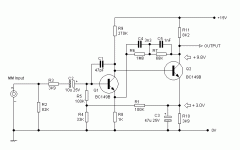

The 47p capacitor is in the wrong place. Input capacitor should be much higher
Brian
Brian
I don't see a coupling cap between the front end and power MOSFET. The cap on the output of the MOSFET needs to be in series with the headphones or they'll just burn up. MOSFET is running class A and needs a good heatsink. It's probably not going to be stable. Hopefully the schematics above are not reflective of what you've built!
It looks like the load impedance the RIAA network drives in your circuit is way too low, so the signal from the RIAA network, which is high in impedance, has little effect on it, sorta like driving a near short circuit.I've taken the liberty of copying your schematic here for ease of reference:
View attachment 1172350
There have been many 2-transistor RIAA preamps built over the years. Many/most receivers used some variation. Back in the '70s there was a company, Ace Audio, that had a simple but decent one. Schematic is here, just to give an idea of the values. They did use a PNP, unlike the circuit above. If you don't like that one, there are hundreds more to choose from!
http://www.conradhoffman.com/papers_lib/AA_phono.jpg
http://www.conradhoffman.com/papers_lib/AA_phono.jpg
It's a frequency-dependent NFB network. It is meant to have little effect at LF, rising with frequency according to the RIAA transfer characteristics as the shunt capacitors lower its impedance.It looks like the load impedance the RIAA network drives in your circuit is way too low, so the signal from the RIAA network, which is high in impedance, has little effect on it, sorta like driving a near short circuit.
The gain is certainly too high, but that's only one of many problems with this circuit.
The original problem was the 47pF input capacitor imposing a rising frequency response counteracting the RIAA's falling response.
- Home
- Source & Line
- Analogue Source
- RIAA network has no effect