Well, I did not know where to post this thread, if the moderators think there is a more appropriate place they are welcome to do so! 🙂
I would like to ask this: in what frequency range does impedance matching become important in order to avoid problems?
For example, I will try to pass a 2.5MHz square (or sawtooth, fast rising or falling edge anyway) to a small capacitor (50-100pF), but with lots of volts in amplitude (50-100). So I wondered:
Let's say I use an RF transformer to step the voltage up. There are 50 ohm transformers available for that purpose. But if I was to terminate the transformer properly, I would have to waste around 50Watts of power on these terminating resistors! 50-100Vpp into 50 Ohms should be something like that.
Then I wondered, what if I just hooked the transformer up and don't match impedances. Is my frequency high enough to encounter problems? A fast (20ns) falling or rising edge might hide frequencies up into 50-100MHz, so the spectrum is broader than 2.5MHz, and that got me into thinking.
And, sadly, I can barely find clear explanations around the web about how to proper match, and when to do so (frequency etc). If anyone knows a good place about all this I would be glad!
One normally uses impedance matching on at least one side to get rid of transmission line reflections and resonances. When the line is much shorter than a quarter wavelength of the highest frequency of interest, there is no need because it can't resonate anyway.
When a transformer is meant for some impedance Z, that basically means that the manufacturer tried to come up with a compromise between magnetizing inductance, spreading inductance, winding capacitances and losses that works well over the intended frequency range when the driving impedance is roughly Z. You would need more specific information to figure out what happens when the impedance isn't even close to Z. That is, you would either have to buy one and measure what happens, or to see if you can find a decent model for the transformer somewhere and simulate or calculate how it behaves with the impedances you want to use.
In any case, for an RF transformer meant to be used in a system that has impedance termination on both sides, if it steps up the voltage, it must have a turns ratio that is 1:n with n > 1, and the intended impedance on the secondary side is then n^2 times the impedance on the primary side. So your transformer can't be designed for 50 ohm termination on both sides and step up anyway.
Many thanks for your answers.
I am aware that not matching impedance results in reflections, so I should insist on when it really matters. This is what is not clear to me yet...
Based on MarcelvdG's comment, I deduce for example that up to 100MHz, I would not encounter weird reflections for a 50 ohm cable say 15-30cm long, since 100MHz 1/4 wavelength is 75cm. So, could I neglect the cables effect in my calculations?
I clearly understand your remark on the 50 ohm transformer specification - this was my thinking initially. Sadly I cannot test many things now that we are in a covid lockdown, which means that I am left with simulating the transformer.
Another question is how to properly terminate - say I have an opamp feeding a 50 ohm cable, that feeds a load on the other side. For correct matching, I should insert a 50 ohm in series with the opamp, and a 50 ohm parallel to the load? Supposing the load is significantly greater than 50 ohm at the frequency of interest? Between these 50 ohm resistors goes the 50 ohm coax.
Yes, the 50R cable should see 50R at each end. Add a shunt 50R resistor where it is necessary.
This is routine in wide band lab test equipment. An external 50R for this purpose is called a terminator.
http://www.farnell.com/datasheets/2615426.pdf
This is routine in wide band lab test equipment. An external 50R for this purpose is called a terminator.
http://www.farnell.com/datasheets/2615426.pdf
Last edited:
It's the wavelength in the cable's dielectric that matters, which is 1/sqrt(epsilon_R mu_R) times the wavelength in vacuum. For a typical solid polyethylene-filled coaxial cable, that's about 2/3 of the wavelength in vacuum (that 2/3 is called the velocity factor).
Even when a cable is electrically short, it can still have an impact on your circuit. Unlike a long cable, you can model a short cable with a simple lumped model consisting of a series inductance and a shunt capacitance if that makes it easier to see or calculate what is going on. A typical 50 ohm cable with solid polyethylene dielectric has an inductance of about 250 nH/m and a capacitance of about 100 pF/m. (The square root of the ratio is the high-frequency characteristic impedance and the reciprocal of the square root of the product is the velocity of propagation inside the dielectric.)
In theory, termination at the load side is sufficient to eliminate any reflections and termination at the source side is sufficient to reduce the number of reflections from infinity to 1. When there is only one load, either termination is in in principle sufficient. You often see series termination at the source side in digital and mixed-signal circuits involving fast CMOS logic.
For the wideband lab test equipment that rayma wrote about, it is indeed routine to terminate on both sides. The reason is that, especially at very high frequencies, it is impossible to make the termination impedance exactly 50 ohm. There are always tolerances and reactances that mess up the termination to some extent. With imperfect terminations, the remaining reflections damp out faster when both sides are terminated.
To add to the useful info provided previously, when the base frequency is lowish (2.5MHz f.e.), but the signal contains higher harmonics (fast edges), it is generally possible to use a selective termination as a tradeoff: a 50ohm resistor in series with a small cap.
It will terminate and damp HF contents, but will avoid the large dissipation caused by a pure 50R.
The solution is not perfect, and some tweaking might be necessary, but it can be useful
It will terminate and damp HF contents, but will avoid the large dissipation caused by a pure 50R.
The solution is not perfect, and some tweaking might be necessary, but it can be useful
Thanks for the wonderful info.
How could you then model a long cable run? Could you break it in as many lumped LC elements you can? I remember doing so in a lab experiment in the polytechnic.
As far as the transformer is concerned, I do realize that it has a primary and secondary inductance, plus their corresponding leakages. So, these values could mess (resonate) with your load if not selected carefully, right? This is my crude finding from some quick simulations.
I don't completely understand why you should see the inductance as a load. Physically, it is the first thing that comes in mind, because you just drive an inductor with your input source, and then this inductor, galvanically isolated, creates the magic 🙂P) flux needed to produce a signal on the other end. But depending on what is in the other end, you can't do everything you want on the primary side - which means that you don't just see an inductor.
My basic understanding would lead me to believe that if these inductors are way higher in impedance than the secondary load in the frequencies of interest, they would not interfere with the circuit's behavior. Is that accurate?
Can you post your simulation or your provisional schematic (even if it is embryonic or rudimentary)? It will serve as a concrete base for discussion, otherwise we are going to waste time in irrelevant generalities.
Note that simulators can simulate actual transmission lines, there is no need to resort to a lumped model.
Note that simulators can simulate actual transmission lines, there is no need to resort to a lumped model.
Thanks for the wonderful info.
How could you then model a long cable run? Could you break it in as many lumped LC elements you can? I remember doing so in a lab experiment in the polytechnic.
Both for simulations and for hand calculations, you can either model a long cable as a transmission line or as a series of short lines that are all modelled as LC sections. Modelling it as a transmission line is usually easier, but do whatever you find more convenient.
As far as the transformer is concerned, I do realize that it has a primary and secondary inductance, plus their corresponding leakages. So, these values could mess (resonate) with your load if not selected carefully, right? This is my crude finding from some quick simulations.
I don't completely understand why you should see the inductance as a load. Physically, it is the first thing that comes in mind, because you just drive an inductor with your input source, and then this inductor, galvanically isolated, creates the magic 🙂P) flux needed to produce a signal on the other end. But depending on what is in the other end, you can't do everything you want on the primary side - which means that you don't just see an inductor.
My basic understanding would lead me to believe that if these inductors are way higher in impedance than the secondary load in the frequencies of interest, they would not interfere with the circuit's behavior. Is that accurate?
The magnetizing inductance is in parallel with the transformed load impedance and the leakage inductance is in series with it, so ideally you want the impedance of the magnetizing inductance to be much greater than the transformed load impedance and the impedance of the leakage inductance to be much smaller than the transformed load impedance. Good transformers have a large ratio of the magnetizing inductance to the leakage inductance, but the ratio is always finite. When the ratio of the highest frequency of interest to the lowest frequency of interest is very large, it gets difficult to manufacture a transformer with high enough magnetizing inductance for the lowest frequency and low enough spreading inductance for the highest frequency - which is one of the reasons why good audio transformers are so expensive.
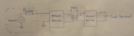
Here is the schematic.
The capacitive load could also be a piezo element (I know it has different model, and I would adjust the matching networks according to it).
I am not being lazy in simulations, I love them, and I will simulate a transformer once I have its data (for RF, they come in s-parameter form). I just want to know what to look for, the theoretical background, for obvious reasons. Maybe even if there is not something suitable in the market I could wind one on my own.
MarcelvdG: Then it is close to what I imagined, so maybe I would have to consider transformers with high-impedance primaries for my purpose (that is, low magnetizing inductance).
What I did not illustrate in the schematic is a coax cable going to the load, but I considered it part of the matching network as a block diagram, I hope it is not confusing.
Attachments
As is often the case, the devil is in the detail, and your block diagram leaves many important (quantitative) details out.
For example, what importance has the fidelity: the transmission of the edges f.e., and how fast are the edges?
If you accept clean and soft edges of 100ns, when the original waveform has 10ns, you can use the leakage inductance constructively, in combination with other equalizing passives. If you need a perfect fidelity, things are going to be more complicated.
From the few elements you provided, I think that if your driver has a ~0 output impedance, you can probably get away with a directly driven transformer, followed by a 50 ohm resistor to drive the cable and the piezo transducer: the 50R should tackle the back reflections and tame resonances induced by the non-ideal Xformer parameters.
Of course, all of that depends on the actual, quantitative parameters.
Opting for a cable having having a Zo>50ohm could probably help: some less common types of of cables have a Zo in the hundreds of ohms.
You model the piezo element like a simple capacitor; that's OK if you operate it very far from its mechanical resonance, but it is completely wrong if you work at or near a resonance (electromechanical devices have many resonances).
Think of a quartz crystal: if you measure it with a normal capacitance meter, it will just display a few pF's, but its motional parameters near a resonance measure in kilohenries and femtofarads.
A short length of coaxial cable might also look like a cap of a few tens of pF, but it will behave very differently with a fast stimulus, and a lumped model using LC elements could be equally wrong.
Numbers, numbers: that's what really counts.
For a 2:1 transformer, you can use a bifilar transformer wired as an autoformer: it will have a very low leakage, and a low voltage CM choke can be used. They are cheap, common and come in infinite varieties.
They do not tolerate DC component though (that will be the case with all transformers having a very large magnetizing/leakage inductance ratio)
If you put flesh (numbers) on the bones, we can help you select the right components.
One last thing: your problem doesn't seem uncommon: I have seen a similar topic some time ago on this forum, and there are probably similar questions elsewhere, meaning a SOTA solution probably already exists. Which doesn't mean that it is impossible to improve SOTA, but it would be a good idea to start from existing, working solutions even if they aren't perfect or perfectible
Transmission lines remind me of a software engineer I knew.
He wrote a software keyboard routine for some equipment.
For the life of him he really struggled to get it to work.
He resorted to taking 100 samples and using most common sample.
His mistake was that the processor sent out keyboard scan on a long ribbon cable.
As an electronics engineer I know ribbon cable is capacitive and is also a transmission line.
He was getting a delay down the ribbon cable and so getting indeterminate results coming back.
I popped in a small delay before reading back and it all became much easier for him.
I also got a Z80 computer system to fix as it kept getting corrupted memory.
They were convinced the DRAM was capacitive and causing delays on address and data bus. In the end it was quite a simple fix as they didn't know the Z80 has a 7 bit refresh and not 8 it. So it needed to have the 8th bit generated somehow.
I also worked on a telecoms conferencing system which had quite a long upfront speech message to play out. It was a few megabytes of DRAM. We couldnt get it to work. In the end a Texas Instruments engineer came out to have a look. Transmission line problems, put small resistor in series with each data line and that fixed it.
If you accept clean and soft edges of 100ns, when the original waveform has 10ns, you can use the leakage inductance constructively, in combination with other equalizing passives. If you need a perfect fidelity, things are going to be more complicated.
From the few elements you provided, I think that if your driver has a ~0 output impedance, you can probably get away with a directly driven transformer, followed by a 50 ohm resistor to drive the cable and the piezo transducer: the 50R should tackle the back reflections and tame resonances induced by the non-ideal Xformer parameters.
Of course, all of that depends on the actual, quantitative parameters.
Opting for a cable having having a Zo>50ohm could probably help: some less common types of of cables have a Zo in the hundreds of ohms.
You model the piezo element like a simple capacitor; that's OK if you operate it very far from its mechanical resonance, but it is completely wrong if you work at or near a resonance (electromechanical devices have many resonances).
Think of a quartz crystal: if you measure it with a normal capacitance meter, it will just display a few pF's, but its motional parameters near a resonance measure in kilohenries and femtofarads.
A short length of coaxial cable might also look like a cap of a few tens of pF, but it will behave very differently with a fast stimulus, and a lumped model using LC elements could be equally wrong.
Numbers, numbers: that's what really counts.
For a 2:1 transformer, you can use a bifilar transformer wired as an autoformer: it will have a very low leakage, and a low voltage CM choke can be used. They are cheap, common and come in infinite varieties.
They do not tolerate DC component though (that will be the case with all transformers having a very large magnetizing/leakage inductance ratio)
If you put flesh (numbers) on the bones, we can help you select the right components.
One last thing: your problem doesn't seem uncommon: I have seen a similar topic some time ago on this forum, and there are probably similar questions elsewhere, meaning a SOTA solution probably already exists. Which doesn't mean that it is impossible to improve SOTA, but it would be a good idea to start from existing, working solutions even if they aren't perfect or perfectible
One by one!
As I mentioned in previous posts (but wasn't clear about it) I would like edges in the territory of 20ns, which means a 50-100 MHz bandwidth, and that is why I asked in the first place.. A little mistake could lead to unwanted response. So I need fidelity, yes.
About the load, I know the piezo model, I have used one in the past, and since my base frequency is at 2.5MHz and this one resonates at about 13MHz, possibly (haven't constructed the model yet, I have the measurements to do so and I will), I know I must properly model it and not as a capacitor. Eventually I will design the thing for the piezo, but I started from a cap, I know the difference is significant.
Its low frequency capacitance is around 70-75pF, that I know.
The waveform will be (at worse) sawtooth, meaning I will have a falling edge of 20ns (desired, if not better). And the amplitude will be 50-100Vpp at the load end, which could raise a question about selecting a proper transformer - or as you said, a choke. This seems a good idea since RF transformers found with ease are 0.25W max.
Why am I bringing this up? Charging a capacitor of 100pF with 50 in 2.5MHz sawtooth would not require more than mils of power (but current, yes, it will reach 300mA), so even though my RF transmitted power will be small, (a) I don't know if the field density will be within spec for such a current and (b) using low resistors for terminations could lead to a huge waste of power, so I would need to redesign the source to a high-power one.
One last thing: your problem doesn't seem uncommon: I have seen a similar topic some time ago on this forum, and there are probably similar questions elsewhere, meaning a SOTA solution probably already exists. Which doesn't mean that it is impossible to improve SOTA, but it would be a good idea to start from existing, working solutions even if they aren't perfect or perfectible
Forgot to mention that I did not find any relevant threads in the forum, that is why I created this one... Do you happen to have any clue about the location of the thread you mention?
I had a look, but of course I couldn't locate it.
I found this, which is vaguely related: Power stage for piezo-crystal ultrasound transducer.
and this, elsewhere:
http://www.precisionmechatronicslab.com/wp-content/publications/D08a.pdf
I found this, which is vaguely related: Power stage for piezo-crystal ultrasound transducer.
and this, elsewhere:
http://www.precisionmechatronicslab.com/wp-content/publications/D08a.pdf
Many thanks for that, I am going through these articles.
As far as using a transformer or a common mode choke, is there a way of determining the appropriate values for the numbers I presented? I am currently working on extracting an RF transformer's model to gain a clue about the values of primary inductance that could be useful.
As far as using a transformer or a common mode choke, is there a way of determining the appropriate values for the numbers I presented? I am currently working on extracting an RF transformer's model to gain a clue about the values of primary inductance that could be useful.
- Home
- Design & Build
- Construction Tips
- RF impedance matching