Greetings Friends. I've reworked the schematic for the SE EL84 project amp I posted a few weeks ago. Someone pointed out that the PT is under-rated for the current demands and might not have a long life. Looking at the EL84 datasheet, I see that the current demands of an EL84 wired in Triode mode are ~10-12mA lower than that of Pentode mode:

So I'm thinking I should swap some 270 ohm 5w resistors in there and rewire things til they look like this:

With the larger K resistors, I expect b+ to increase, and I will have to add a dropping resistor before the choke in the power supply. Should still have a margin of 15mA or so.
The datasheet shows the Load Resistance of the tube drops from 5k to 3.5k in triode mode. I do have a pair of Edcor GXSE10-3.5K I could swap in with a minimum of chassis rework, or just leave the 5k in there. And I still have the switch I could use to select between triode and UL if I really needed the extra volume.
I'd end up with something like the Decware triode amp. Whaddya think?
So I'm thinking I should swap some 270 ohm 5w resistors in there and rewire things til they look like this:
With the larger K resistors, I expect b+ to increase, and I will have to add a dropping resistor before the choke in the power supply. Should still have a margin of 15mA or so.
The datasheet shows the Load Resistance of the tube drops from 5k to 3.5k in triode mode. I do have a pair of Edcor GXSE10-3.5K I could swap in with a minimum of chassis rework, or just leave the 5k in there. And I still have the switch I could use to select between triode and UL if I really needed the extra volume.
I'd end up with something like the Decware triode amp. Whaddya think?
I'd leave the 5k in. Does your power transformer get very warm?

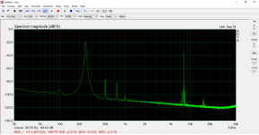
With 3k5 load, the distortion at least doubling (vs. 5k).
If you connect 1000uF to output (where did you see this .... ?) both the LF and HF behaviour will degrading.
Estimated power (even with 3k5 load) rather 1.5W than 4W (in A1 mode, in this operating point).
p.s. Which type of OPT do you want to use?
If you connect 1000uF to output (where did you see this .... ?) both the LF and HF behaviour will degrading.
Estimated power (even with 3k5 load) rather 1.5W than 4W (in A1 mode, in this operating point).
p.s. Which type of OPT do you want to use?
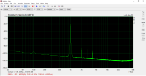
Yup, no way getting 4W in A1. 5K results in a slightly lower output power but lower distortion.Estimated power (even with 3k5 load) rather 1.5W than 4W (in A1 mode).
The trouble with these UL/triode option switches is that it take 2 or 3 flips to decide which is preferable and it's always the UL mode. The two modes really require two different OPT primary Z's. If you will do some research on UL you'll find that to get the most from it you need an OPT with 23% screen tap. You still need to rework the 6DJ8 operating point, too, instead of the starved condition you are trying to run it in. Your PT will drive a conventional amp with pentode mode and a 12AX7 with no problem, and you can use some GNFB, too.
Last edited:
I'm putting together an EL84 triode type PSE amp, and you may decide that a couple in parallel would lower the Rp and give you a bit more power.
Since a pair will give me enough output I'm going to use E80L instead of EL84. That's a nice valve, different pinout, gold pins. Just one idea.
Since a pair will give me enough output I'm going to use E80L instead of EL84. That's a nice valve, different pinout, gold pins. Just one idea.
I rigged up a PSE E80L output stage and it's pretty good. Very clean with good tone. Not the same pinout as an EL84. 5K OPT, Type 26 driver stage in filament bias.

More B+ current from the same power transformer?
Voltage First:
With a capacitor input B+ filter, the limit of B+ voltage is 1.414 times the primary rms voltage.
(not including rectifier voltage drop, primary DCR and secondary DCR voltage drops, etc.).
With a choke input B+ filter, the limit of B+ voltage is 0.9 times the primary rms voltage.
(not including rectifier voltage drop, primary DCR and secondary DCR voltage drops, etc.).
That is a difference of 1.57 times more B+ in a cap input filter, versus a choke input filter.
However, it is never that large of a difference, because of the much larger peak current in the cap input filters; so the primary DCR and secondary DCR voltage drops are much larger with cap input filters, versus choke input filters.
Current Next:
But the Limit of B+ current is 1.57 times more B+ current from a choke input supply, versus the B+ current from a capacitor input filter supply, when the same power transformer is used.
Your Mileage May Vary.
It is a Mean thing to say that Karl Friedrich Gauss was an Average man, who was Centered on his Gaussian Curve.
You cannot use the same transformer VA rating.
With L input the transformer VA rating has only to be 1.1 bigger than the dc load in W.
With fullwave bridge, or voltage doubler into C input, you need normally something around 1.6VA per W dc load, with big caps often more.
How much more depends on conduction angle.
With fullwave centertapped the secondary should be designed with a higher VA rating than the primary, because half of the time only half winding of the winding has to supply all the power whilst the other is idle only taking up space.
Last edited:
What i was trying to point out is, that some cĺever manufacturer migth want to make a transformers VA rating looking bigger than it actually is.
Say, a transformer is rated the following way:
Secondaries
450-0-450V, 0.2A rms
5V 5A rms
6.3V 5A rms
That migth look like 180VA+25VA+31.5VA= 216.5VA total.
But since this transformer is clearly designed for CT tube rectification the primary surely is NOT not designed to be loaded with 216.5VA because it would be a waste.
If you would fully load the 5A windindings, and decide to use that avaiable 900V with a bridge rectifier, or doubler, and load it with the rated 0.2Arms current the primary would be overloaded.
If the restricting primary VA rating is unknown, life could be short, even without exceeding any of the manufacturers secondary rms current limits.
Last edited:
For a good document that show the secondary ratings versus different rectifier circuits, different filters, and full and center tapped secondaries,
and the DC load current ratings, search the Hammond transformer web site.
Half wave, full wave, bridge, center tapped, full secondary, voltage doubler, etc.
Resistor load, capacitor filter, and inductor filter.
Generally:
If the volts and current are sinusoidal, and in phase, then Volt x Amps = Watts (VA = W)
For other wave shapes and different current versus voltage phases, Volt x Amps and Watts are not equal.
Given sinusoidal current and sinusoidal voltage that are 25.8 degrees out of phase, the Cosine of 25.8 degrees is 0.9
My choke input power supplies typically run at a power factor of 0.9.
So, for those power supplies, Watts = (Volt x Amps) x 0.9.
100 Volt x Amps x 0.9 = 90 Watts.
So, for a VA of 100, you get 90 Watts power out.
If the sinusoidal current and sinusoidal voltage that are 60 degrees out of phase, the Cosine of 60 degrees is 0.5.
That means for 100 VA, you only get 50 Watts power out.
Oh, 1.6 / 1.1 = 1.45, that is close to my less conservative factor of 1.57 in my Post # 10
So, for example, a center tap and 2 diode full wave rectifier that drives a choke input filter, can safely output about 1.45 times more DC current than the DC current that a capacitor input filter can safely output.
For another example, a full wave bridge rectifier across a whole secondary winding, that drives a choke input filter, can safely output about 1.45 times more DC current than the DC current that a capacitor input filter can safely output.
Pick your secondary, rectifier circuit, etc.
Then, typically the choke input filter can output about 1.45 more DC current than a capacitor input filter.
But just do not forget, the choke input filter has far less DC voltage out, versus the capacitor input filter.
To get the same DC voltage out of the choke input filter, the secondary voltage has to be greater than the secondary voltage for a capacitor input filter.
Last edited:
The important limit to respect is the secondary amperage rating at the rated primary input voltage. The PT has no idea of what type of filter is on the other side of the rectifier. Since the PT, rectifier and filter is a series circuit, the load current out of the filter is the same RMS current through the PT secondary. PT's do not come with a conversion equation to use against the rating with respect to the filter type. There are too many variations/combinations of cap/choke designs. Filter performance is for the engineer to figure out. Lab 101.
@rufus74pz,Hello.
Instead of the PSE on EL84, I recommend the EL86 circuit. I built such an amplifier 10 years ago and everyone who listened to it rated it higher than the EL84 one. Measurement made at 4.5W
Piotr
Your experience is of great interest to me, and possibly OP. Would you be willing to share the schematics, the operation conditions of the output tubes and output transformer characteristics? PM me if preferred.
Last edited:
20to20,
You said: "There are too many variations/combinations of cap/choke designs."
Did you take a look at the Hammond document (it documents about 90% of the possible combinations.)
The power transformer secondary 'senses' the amount of (Current)squared x DCR heating it "experiences".
It either runs hotter, or it runs cooler (relative to capacitor input filter versus choke input filter, respectively).
For a specified DC load current, mA:
A typical capacitor input filter has Peak current that is often 5 to 10 times or even more times, versus the DC load current.
The (Current)squared x DCR heating losses integral caused by a capacitor input filter;
are Much larger versus:
The low (Current)squared heating losses integral of a choke input filter (choke input has average current, not large peaks).
And then there is the issue of B+ ground loop currents:
Capacitor input filter, high current transient peaks that have lots of high frequency harmonics. UGH!
It even can reflect those transients back to the filament secondaries and the primary all the way back to the power line that powers the rest of your Hi Fi Stereo system components.
Choke input filter, average current that is almost all low frequency. No transients to reflect back to the filament secondaries and primary that is connected to your other Hi Fi stereo system equipment.
I admit it, this is about designing it one way or the other in the beginning; It is not about changing it after the power transformer has already been purchased.
The choice is up to the designer when he specifies the power transformer.
Last edited:
Actually, that is what i also tougth to be true, but today i came across a paper where,amongst other things, transformer utilization of bridge and CT was compared. According to that study, a transformer loaded with bridge rectifier has a utilisation factor of 0.813, primary, same as secundary, VA=1.23Pdc.My choke input power supplies typically run at a power factor of 0.9.
So, for those power supplies, Watts = (Volt x Amps) x 0.9.
100 Volt x Amps x 0.9 = 90 Watts.
So, for a VA of 100, you get 90 Watts power out.
If the
Same paper, CT, primary VA 1.23Pdc, secondary VA 1.75Pdc, utilisation factor 0.671.
How about that?
Not the same as power factor - utilization factor is output VA / input VA. The center-tap circuit suffers since each half of the secondary carries current for less than 50% of the time, regardless of the filter circuit used. With no filter, (rectifier with resistive load only) primary utilization would be 1.0, secondary 0.707.
Actual efficiency numbers would be lower, due to losses in transformer, rectifier losses, capacitor ESR, choke losses.
Actual efficiency numbers would be lower, due to losses in transformer, rectifier losses, capacitor ESR, choke losses.
Did i mention pf?
In a transformer with rectified dc load the transformer utilization factor is Pdc/VA, where VA = VApri/2+VAsec/2.
A 100VA transformer bridgerectified has a utilisation factor of 0.813 and therefore the Pdc is 81.3W, not 90W.
In a transformer with rectified dc load the transformer utilization factor is Pdc/VA, where VA = VApri/2+VAsec/2.
A 100VA transformer bridgerectified has a utilisation factor of 0.813 and therefore the Pdc is 81.3W, not 90W.
Last edited:
Sorry Bavis, i came across a bit too convinced and harsh, am still a bit puzzled and transformer utilisation may be not so clear cut
as i tougth it is with L input...
Say,we have a 1ph transformer, secondary feeding a bridge (disregarding all losses) and this 3 different load scenarios:
as i tougth it is with L input...
Say,we have a 1ph transformer, secondary feeding a bridge (disregarding all losses) and this 3 different load scenarios:
- resitive load (sinus current)
- infinite inductance (perfect squarewave current)
- minimum inductance (not so square current)
- Home
- Amplifiers
- Tubes / Valves
- Reworking this SE EL84 project to Triode to save some mAs?