So, I had a previous thread here wherein I used an instrumentation amplifier with mixed results, to act as a preamp for a balanced piezo pickup. It was determined that I had unnecessarily used low-value caps in a HPF on the input, and also I was using an inst amp IC that didn't have jfet inputs, which contributed to noise.
I decided to try again, this time using an instrumentation amp built from opamps instead of a single IC. I feel like my component selection was really good, and I checked and triple checked my schematic. But, I soldered everything together with a new board today, and got nothing but hum. I checked all my connections and all are solid.
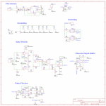
Went back to my schematic, and found one flaw! I connected the wrong leg of the difference amplifier part of the inst amp, to ground. If you look at the schematic below, R-I7 and R-I8 connections are switched from where they should be. This makes the + leg of IC-I2.2 biased to the input signal, and the - leg biased to ground, instead of vice versa.
My questions:
1) Would this error alone cause buzzing and no audio to pass through (except buzz)?
2) Are any other huge errors present here that I'm missing? I've looked at this so many times, but I feel like I'm missing something else.
I appreciate everyone's patience, this is only my second venture into something built from scratch (not using others' schematics).

R17 and R18 connections can NOT be switched from the standard connection. R18 must go to ground.
Positive feedback will not work.
Reduce all the values of R13 through R18, and the 400k RIGAIN, by a factor of 1/20 each.
But do you actually want input gain of only x1.5 before the volume control?
If you want more gain than that, reduce further only the IGAIN proportionately.
High impedance levels at the inputs require proper practices.
The active filter stage probably needs an input buffer after the volume control.
Why 100k volume control, better to use 10k instead.
Also make sure the XLR is wired right.
Last edited:
OK, so this gives me some stuff to work with. Thank you!
I didn't intend to do positive feedback, that was totally just an error on my part as I must not have noticed how the symbol was oriented 🙁.
So, I did quite a bit of googling on what value resistors to use for the instrumentation amp part, and I never found anything definitive. Instead of 100k I need to do like 5k, and then obviously 20k for the gain resistor? That sounds good.
As for the amount of gain, I did intentionally set this fairly low. I may bump it up to a bit more, but the pickups I'm using this with are fairly hot. Maybe a gain of 4 or 5 might be ok. So my gain resistor value goes down further.
Will switch to 10k log volume pot.
Yes, the XLR is correct, of that I am certain.
I appreciate the review! I will rework this and probably post it here before I jump the gun again and try building.
Post photos of the pcb and layout. Or is this just on a breadboard now?
The 40M input requires more than the usual care, such as parts on teflon standoffs, etc.
The active filter requires a low source impedance, so the volume control probably needs a buffer after.
Or you may be able to locate the volume control after the active filter instead.
The 40M input requires more than the usual care, such as parts on teflon standoffs, etc.
The active filter requires a low source impedance, so the volume control probably needs a buffer after.
Or you may be able to locate the volume control after the active filter instead.
Last edited:
OK, here's what I changed so far:
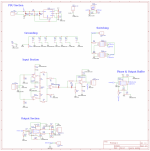
Resistor values for instrumentation amp were lowered, gain was raised (to 5). Volume knob changed to 10k log, and switched place with the active filter. Instrumentation amp feedback error fixed.
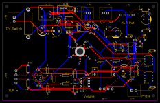
I did use an autorouter, but was pretty careful about my part placement and made sure the high impedance differential pairs were short and of the same length.


Edit: my schematic still says 400k for the gain resistor. It's 3.3k. My bad
Resistor values for instrumentation amp were lowered, gain was raised (to 5). Volume knob changed to 10k log, and switched place with the active filter. Instrumentation amp feedback error fixed.
I did use an autorouter, but was pretty careful about my part placement and made sure the high impedance differential pairs were short and of the same length.


Edit: my schematic still says 400k for the gain resistor. It's 3.3k. My bad
I know a piezo has to have a resistive load across, but 40M? I do remember making piezo pickups out of Sonalert buzzers and always had to put a resistor across the unit to get it to pickup. OK, I dug through my junk box and found one I'd constructed; resistor embedded in epoxy so I cant read it. Measures ~1M... FWIW!
I would start the pcb over. Since you won't have a ground plane, first adjust component placement for best signal flow.
Then add connections for the power supply lines, and place very close decoupling capacitors at each package.
Next add the components and close connections for the piezo inputs.
Then add components and close connections for all of the inverting inputs, keeping the routing short and direct.
That is, any component connected to an inverting input should be very close to that input, including the R-IGAIN.
Avoid routing lines between close pads of connectors or op amps. Try to use components as jumpers, for example.
- Home
- Source & Line
- Analogue Source
- Reworked my piezo preamp design; failed