I haven't built this yet, and I have no experience building audio amplifiers, so I'd appreciate if someone could comment on this, and what I can improve before I go ahead and build it.
I just noticed a typo. I typed input at the output instead of output. Oh well, doesn't matter. The 25V is also a guess, that's not definite.

A few other questions:
I'm trying to save not spend a lot on this project, and I have two 12-0-12 transformers (one from a dead guitar amplifier, one from a dead boom box). Can I use them in series to get 24-0-24? My only problem is I'm not entirely sure of their power ratings, as they aren't marked other than the 12v. If it helps, both were fused for 6A in their original devices, so if I go with a 6A fuse in my power supply, will that be fine?
I have two sets of speakers, one 4-ohm 20W, one 4-ohm 30W. I'd like to make two monoblocks, and drive two speakers in series off each monoblock (one 20W, one 30W). This is because in tests I did with another amp, the 30W speakers have weak treble, and the 20W speakers have weak bass, but they sound nice together.
What power do I need for both these speakers? I was going with speaker power * 1.8, but do I use the 20W, 30W, or both for 50W? Should I just aim for the maximum I can get out of my power supply (~33V)?
Do I used the 8-ohm curve or the 4-ohm curve on the LM3886 datasheet? (I'm guessing 8-ohm as that's the total load).
Right now I'm planning on using a regulated power supply (LM338) to drop from the ~32V I get using 24-0-24 to whatever voltage I need.
Power supply, currently set to 24.3V (based on the LM338 datasheet and Building a Gainclone chip amp with snubberized PSU. with some modifications):
Note: the 24V AC power supplies are instead of the dual 12-0-12 transformers, just for simulation purposes.

Edit: Another question:
Some LM3886 designs I've seen have a ~5hz high-pass filter at the input, and ~30-50kHz low-pass at the output. What's the point of these - just removing extra junk that you can't hear anyways?
I just noticed a typo. I typed input at the output instead of output. Oh well, doesn't matter. The 25V is also a guess, that's not definite.
A few other questions:
I'm trying to save not spend a lot on this project, and I have two 12-0-12 transformers (one from a dead guitar amplifier, one from a dead boom box). Can I use them in series to get 24-0-24? My only problem is I'm not entirely sure of their power ratings, as they aren't marked other than the 12v. If it helps, both were fused for 6A in their original devices, so if I go with a 6A fuse in my power supply, will that be fine?
I have two sets of speakers, one 4-ohm 20W, one 4-ohm 30W. I'd like to make two monoblocks, and drive two speakers in series off each monoblock (one 20W, one 30W). This is because in tests I did with another amp, the 30W speakers have weak treble, and the 20W speakers have weak bass, but they sound nice together.
What power do I need for both these speakers? I was going with speaker power * 1.8, but do I use the 20W, 30W, or both for 50W? Should I just aim for the maximum I can get out of my power supply (~33V)?
Do I used the 8-ohm curve or the 4-ohm curve on the LM3886 datasheet? (I'm guessing 8-ohm as that's the total load).
Right now I'm planning on using a regulated power supply (LM338) to drop from the ~32V I get using 24-0-24 to whatever voltage I need.
Power supply, currently set to 24.3V (based on the LM338 datasheet and Building a Gainclone chip amp with snubberized PSU. with some modifications):
Note: the 24V AC power supplies are instead of the dual 12-0-12 transformers, just for simulation purposes.
Edit: Another question:
Some LM3886 designs I've seen have a ~5hz high-pass filter at the input, and ~30-50kHz low-pass at the output. What's the point of these - just removing extra junk that you can't hear anyways?
Last edited:
What's the idea with the 1 uF in series with 20 kohm in the feedback path?
I recommend adding Zobel and Thiele networks. They are needed for stability with capacitive loads (i.e. long speaker cables or electrostatic speakers).
I suggest revisiting the decoupling capacitors.
I suggest adding a capacitor across the 43 kOhm Rmute to avoid clicks and pops when the amp un-mutes on start-up.
For a while, I've been writing an LM3886 design guide. It's on my website: "Taming the LM3886". I suggest you read through it.
~Tom
.
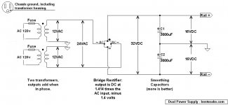
The circuit below is possibly of interest for using your two power transformers. The power available is the rating of the smallest transformer. If one or both transformers heat up, turn down the amp volume--or unplug, of course.
<< both were fused for 6A in their original devices, so if I go with a 6A fuse in my power supply, will that be fine? >>
Yes. The way it works is:
Transformers in series (as shown): secondary voltage doubles, amperage remains the same.
Transformers in parallel (not shown): secondary voltage remains the same, amperage doubles.
IMPORTANT: Do not wire transformers in parallel. Small phase and voltage errors can add up and cause unpleasantness. Wired in series is OK.
Additional information: watts = volts x amps = VA
.
Attachments
Last edited:
.
<< a ~5hz high-pass filter at the input, and ~30-50kHz low-pass at the output. What's the point of these - just removing extra junk that you can't hear anyways? >>
No, and it's wise to leave them in if you build that circuit.
The actual answer is ridiculously complicated, involving math symbols you've never seen unless you're at least a second year engineering student. This is a situation where faith is the answer.
The whole idea behind "chip amps" is that the engineering is already done for us, and compressed into a neat little black package. All we do is bolt things together using some rules of thumb.
But it remains a fact that the engineering involved is complex, which means that adding or subtracting parts for no known reason rarely accomplishes anything good except by luck.
My own thinking is that faith belongs with the team of engineers who designed the thing in the first place. They designed a chip for a specific purpose, to work in a specific circuit, and they publish that circuit in the data sheet as the Typical Application. Build that circuit and you cannot possibly fail. Build some other circuit, one the engineers didn't design for, and...well hey, what do I know.
.
What's the idea with the 1 uF in series with 20 kohm in the feedback path?
Not quite sure the point of it myself, it was suggested in the data sheet. Personally I don't like it, and I'm thinking of removing it.
I recommend adding Zobel and Thiele networks. They are needed for stability with capacitive loads (i.e. long speaker cables or electrostatic speakers).
Thiele network unnecessary as the speakers and amp are all being assembled in one box, close together, but I'll put one in anyways in case I change it later. I will also add a zobel.
I suggest revisiting the decoupling capacitors.
I'm not entirely sure what to do there - the 100nFs were suggested by the data sheet, and the 220s as I figured it needed more than just 100n as decoupling. Any suggestions? What I have is really just a guess, I'm not knowledgeable on how to choose decoupling caps.
Good idea. Will do.I suggest adding a capacitor across the 43 kOhm Rmute to avoid clicks and pops when the amp un-mutes on start-up.
Will do, thanks.For a while, I've been writing an LM3886 design guide. It's on my website: "Taming the LM3886". I suggest you read through it.
~Tom
.
<< a ~5hz high-pass filter at the input, and ~30-50kHz low-pass at the output. What's the point of these - just removing extra junk that you can't hear anyways? >>
No, and it's wise to leave them in if you build that circuit.
The actual answer is ridiculously complicated, involving math symbols you've never seen unless you're at least a second year engineering student. This is a situation where faith is the answer.
I have a very strong math background, well past all the courses an engineering student would take, I just don't have much of an electronics background. Where would I find that information?
.
<< I have two sets of speakers...Do I used the 8-ohm curve or the 4-ohm curve on the LM3886 datasheet? (I'm guessing 8-ohm as that's the total load). >>
You use the nonexistent 2-ohm curve, since two 4-ohm speakers wired in parallel gives a nominal speaker impedance of 2-ohms.
Wired in parallel, the permissible power to the speakers is the rating of the smallest-rated speaker.
Ummm...you do realize that the speaker situation you're talking about is something of a mess? I'm not saying you can't or shouldn't do it (sure you can & should), I'm just mentioning that it's a mess. Sort of admiring the chaos of it, actually.
In my view you're facing unpredictable results. Build the amp you want to build, and as far as speakers go burn that bridge when you come to it.
.
.
<< I have two sets of speakers...Do I used the 8-ohm curve or the 4-ohm curve on the LM3886 datasheet? (I'm guessing 8-ohm as that's the total load). >>
You use the nonexistent 2-ohm curve, since two 4-ohm speakers wired in parallel gives a nominal speaker impedance of 2-ohms.
Wired in parallel, the permissible power to the speakers is the rating of the smallest-rated speaker.
Ummm...you do realize that the speaker situation you're talking about is something of a mess? I'm not saying you can't or shouldn't do it (sure you can & should), I'm just mentioning that it's a mess. Sort of admiring the chaos of it, actually.
In my view you're facing unpredictable results. Build the amp you want to build, and as far as speakers go burn that bridge when you come to it.
.
Speakers will be wires in series, not parallel. I may have miswritten the first post.
<< I have a very strong math background, well past all the courses an engineering student would take, I just don't have much of an electronics background. Where would I find that information? >>
Sorry, I can't give you specific references. I don't keep such documents since I'm a shadetree mechanic, not an engineer.
But Google around for chip amps, or LM3886, and they'll pop up all over the place. Your main interest would be in .pdf documents, especially with a manufacturer's or college's name involved.
Ummm...I still speak a word in favor of taking a mechanic's approach. This is not pure math, it's applied math, and you have to know the properties of the materials involved.
.
Last edited:
<< Where would I find that information? >>
But anyway here's a starting place. Click anything in the red bar at the top:
LM3886 | Mid/High-Power Amplifier | Speaker Amplifier and Modulator | Description & parametrics
.
But anyway here's a starting place. Click anything in the red bar at the top:
LM3886 | Mid/High-Power Amplifier | Speaker Amplifier and Modulator | Description & parametrics
.
I'm not entirely sure what to do there - the 100nFs were suggested by the data sheet, and the 220s as I figured it needed more than just 100n as decoupling. Any suggestions? What I have is really just a guess, I'm not knowledgeable on how to choose decoupling caps.
I cover that on my Taming the LM3886 page. I could type it all again, but it's easier for me to type it once and refer people to it. I linked to that page in Post #2.
~Tom
I cover that on my Taming the LM3886 page. I could type it all again, but it's easier for me to type it once and refer people to it. I linked to that page in Post #2.
~Tom
Thanks. I read that, and it makes more sense now. I'll switch the decoupling caps to your suggested 4.7uF X7R + 22uF OS-CON and a 1mF aluminum electrolytic.
I also realize now the 1uF should be 50pF, I feel kinda dumb for not noticing that its 50pF in the datasheet.
Attempt #2:

Anything I need to fix/improve? Any help is appreciated.
Thanks,
LANS
Another question I just thought of:
A few days ago I ordered LM3886T samples from TI, which is he package with exposed heat sink tab, not plastic coated. Am I OK using two of these chips on the same heat sink if I ground the insulator, or do I need to order another set of samples with the plastic coated heat sink tab?
I don't mind ordering another set, they're free, but I figures the metal tab ones would transfer heat to the heat sink better.
- Status
- Not open for further replies.
- Home
- Amplifiers
- Chip Amps
- Review of my LM3886 project?