This is the charging base for a multifunction light I bought a few years ago at Lidl (brand Livarno).
The light had begun to malfunction erratically, and I located the problem in the wireless charger.
Here is the schematic:
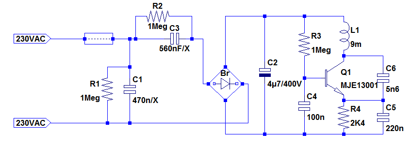
It is a textbook Colpitts oscillator fed by a capacitive supply, and the filter cap C2 had failed.
The problem is that it is precisely an embodiment of a textbook schematic, with everything referenced to the negative rail.
This meant that in addition to the regular ripple, C2 had to withstand all of the resonance current: a serious design flaw.
As a fix, I re-referenced the oscillator to the positive supply, and made a few other improvements: I removed the input suppression capacitor, now unnecessary because the HF residue fed to the bridge had disappeared, and I added a series resistor to the capacitive supply, to reduce current peaks and spare the diodes, and damp transients better.
I also had to upgrade C4 to a 250V type (initially 50V) for the new topology.
I also reduced R4 which was unnecessarily large.
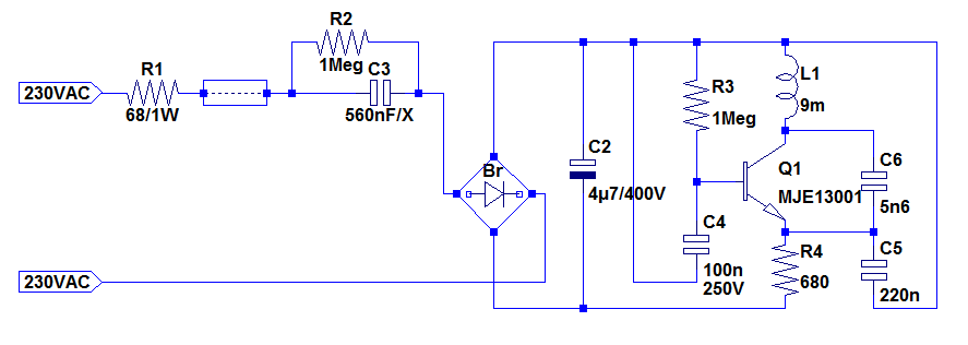
Initially, the rms current through C2 was ~120mA, which the mods reduced to less than 20mA: a 6-fold improvement
The light had begun to malfunction erratically, and I located the problem in the wireless charger.
Here is the schematic:
It is a textbook Colpitts oscillator fed by a capacitive supply, and the filter cap C2 had failed.
The problem is that it is precisely an embodiment of a textbook schematic, with everything referenced to the negative rail.
This meant that in addition to the regular ripple, C2 had to withstand all of the resonance current: a serious design flaw.
As a fix, I re-referenced the oscillator to the positive supply, and made a few other improvements: I removed the input suppression capacitor, now unnecessary because the HF residue fed to the bridge had disappeared, and I added a series resistor to the capacitive supply, to reduce current peaks and spare the diodes, and damp transients better.
I also had to upgrade C4 to a 250V type (initially 50V) for the new topology.
I also reduced R4 which was unnecessarily large.
Initially, the rms current through C2 was ~120mA, which the mods reduced to less than 20mA: a 6-fold improvement
Attachments

Last edited:
I am afraid I can't: firstly, only the transmitter half had problems, and secondly the receiving side is handled by a "jungle" circuit, controlling the power to and from the lithium battery, the wireless input, the power to the two different LED strings and the button functions (and probably also over- and under-voltages). Probably some application-specific IC.
- Status
- Not open for further replies.