Hello all,
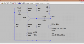
I have here an old Philicorda GM751 Philips organ of which the reverb is broken (it's not fully broken, it's just very very quiet), schematic of the amp section and reverb recovery is attatched. Now, when I touch the springs I can hear them rattling, but that rattling sound is much too quiet compared to when the reverb was still working. This makes me think the problem lies within the reverb recovery stage.
I've already replaced all electrolytics in the organ (and triple checked their polarity!) - by the way, already had this problem before I changed out all the electrolytics -, replaced C679, C680 and C681 (see schematic), measured all resistors in the reverb recovery stage (they measure out just fine) and replaced the AC125 germanium transistor as well. Also checked for cold solder joints (chop stick test) and broken wires, but no results.
Still no reverb, BUT... here's the strage thing and I discovered this by pure coincidence: when I connect a clip wire to ground (chassis) and touch the point where R678, R679 and C676 meet (so I actually short that point to ground) I hear a pop in the speakers and the reverb is back! Again, I didn't connect that point to ground, I simply touched it with the clip wire that is connected to ground. I replaced R678 and R679 just to sure, eventhough they measured out fine, but that didn't make any difference.
I'm also posting this thread on the GroupDIY forum and this is my last reply, which makes it even more puzzling:
I changed out the new C676 100uF cap (just to be sure, new caps can be bad too) and guess what: the reverb worked just perfect after the replacement! Turned the organ off and on, still worked. Switched it off again, went out for dinner, switched it back on: reverb still worked!
Then went to bed, turned on the organ the next morning and guess what... reverb was gone...
Then I did this short-thing again and the reverb kicked in again. Then switched the reverb off on the organ, waited for a minute and switched the reverb back on (switch is named SK10 in the schematic), result: reverb was gone again.
Then did the same short-thing over again and the reverb was back, BUT... now it stays, even when I switch it on/off for a minute, reverb stays. Switch the organ off for a minute, switch it back on and reverb is present. So now it seems to work again, but I bet if I go to bed and switch the damn thing on again in the morning it won't work.
As you guys can see, this is a very weird situation and it seems there is no sense behind it...
I also made that measurement across emitter and base, which is 0.087 volts. Does that mean the AC125 is good? I also measure -4,35V at the emitter (in respect to the ground). Is this normal?
Also tapped all the solder joints and traces on the PCB board, but no results there... I've once red that there are bad solder joints that work well when cold, but after a warm up they don't work anymore... maybe something similar here?
Almost going mad... really hope someone can shine a light on this for me.
Thanks!
Attachments
You have done all the right things so it looks like we need to dig a bit deeper. If the DC voltages around TS676 are correct in both faulty and working states then we need to look elsewhere.
Shorting the junction of R678/679 drastically alters DC conditions (abruptly) and that could just couple through to other stages and briefly correct a problem.
The switch SK10. Do you always get normal sound in the non reverb position ? Its not beyond the bounds of possibility that the switch could have a problem (tarnished contacts) and the abrupt change of DC conditions temporarily clears it.
The 87mv across B and E is a bit lower than I would have imagined for germanium... but not by much, so could well not be a problem. You've changed it anyway so we have to say its OK. Compare with the others for interest.
Thanks for the reply Mooly! Yes I always get normal sound when reverb is switched off. With a Philicorda organ there are two built-in speakers that produce the 'normal' or dry sound. Once you activate the reverb through the SK10 switch the sound is devided between a dry signal in one speaker and a full wet sound in the other speaker.
The SK10 switch is very hard to access and it's not a switch that you can simply remove and take apart to clean. I did switch it a 50 or so times, but so far that was all I could do. It's hard to reach the contacts, eventhough you can see them. Seeing them, they look very well and clean.
I also took the R683 pot meter, which is the reverb mix, apart and cleaned it very well, measured it and it's still a perfect pot. So no issues there.
I've already tried two AC125 transistors, just in case the first replacement was a bad one. But you never know of course... I have here a bunch of new old stock AC125 transistors and it's the first time I use them. Maybe they are all bad, eventhough I bought them from someone who claimed they all worked? How knows...?
You could link the switch out to prove it conclusively, just link positive end of C677 to C651.
If you lift C680, then the base of the transistor will become very sensitive to hum and noise pickup... so you could 'buzz' that point with a screwdriver and see if you get lots of output.
If your DC conditions are correct around the transistor then its a fair bet its basically functional. If the collector is around -10 volts as shown then its going to be OK. I see there are AC125's in the power amp first stage. You could swap it for one of those if there was doubt.
I just linked out the SK10 switch with a clip wire, but no results either. This proves the problem is not in the switch.
Haven't done the thing with C680 so far...
The PCB is a very old one (from 1963) and it doesn't have a coating on the traces, so I can go over those traces with a solder iron and solder and leave a thin fresh solder trace behind. I already did this where the switch is mounted to the PCB and with most other traces (that are related to the reverb recovery) on the power amp board, but so far no results... I also reheated most solder joints, but no results either... Will continue tomorrow.
I touched the trace from the AC125 collector to the 16uF C677 cap and the organ was still on. So I acidentally made a short to ground. And guess what... the reverb kicked in again. But, of course... disappeared again a minute later. So it seems like there are several points where I can do the short-trick-thing to get back the reverb (for a while).
Any one any idea? Seems to be a very hard one...
Any one any idea? Seems to be a very hard one...
🙂 Well I've been working to the idea that you haven't got an oscilloscope... which would nail this fault very quickly.
Can you measure any change in the DC conditions between faulty and working states, on either the transistor we are talking about or the one driving the spring line at the other side.
Also... when it is working and then flips to non working, is the change abrupt or does it pass through a period of fading out/distortion etc ?
(Is it beyond the realms of possibility that the actual spring line could have an intermitent problem ? I'll look at the circuit again later)
Well, I actually do have a scope! But I'm not very familiar with scopes, so if you got any idea, I'm afraid you'll have to guide me through...
I'll try and make some more DC measurements.
I'll try and make some more DC measurements.
That's great.
We can use that to confirm what is happening at the AC125. This transistor is configured to give a voltage gain of around 80 (pretty high because the output of the spring line is very low).
There are two measurements to take, one looking at the output of the stage and the other looking at the input.
Here's what to do,
1/ Set the scope to AC coupling on its input.
2/ Set the sensitivity to a high setting such as 10mv per division initially.
3/ Set the timebase to a slow speed, somewhere around 1 to 5 ms per division.
4/ Connect the scope probe ground lead to any convenient ground point in the amp.
5/ Connect the probe tip to the collector of the AC125.
Now we test the scope by you playing a note around middle C and also by you using your 'shorting trick' to get it all to work. You should see the AC voltage displayed on the scope. Adjust the scopes sensitivity and the main organ volume control until you get a reasonably full display on the screen.
That gives us a working reference point.
When the fault appears you need to confirm that the AC voltage has disappeared. If it has then the fault is at or before this point. If it doesn't then its after.
Assuming its before then we do the same test but this time we try and look at the voltage on C680 direct from the spring line. This AC voltage will be around 80 or more times smaller, so turn the scope sensitivity up to see it and to gauge what its normal working level is. Again we compare faulty and non faulty states or operation.
Depending what this shows we can then move to the input of the delay line on R685. The voltage here will be much higher so turn the scope sensitivity down. Again compare working and non working states.
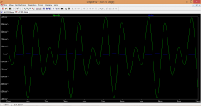
This shows you the kind of thing to expect. Notice the scale and how much gain the signal sees from input to output. The input voltage is in blue, the output in green.
We can use that to confirm what is happening at the AC125. This transistor is configured to give a voltage gain of around 80 (pretty high because the output of the spring line is very low).
There are two measurements to take, one looking at the output of the stage and the other looking at the input.
Here's what to do,
1/ Set the scope to AC coupling on its input.
2/ Set the sensitivity to a high setting such as 10mv per division initially.
3/ Set the timebase to a slow speed, somewhere around 1 to 5 ms per division.
4/ Connect the scope probe ground lead to any convenient ground point in the amp.
5/ Connect the probe tip to the collector of the AC125.
Now we test the scope by you playing a note around middle C and also by you using your 'shorting trick' to get it all to work. You should see the AC voltage displayed on the scope. Adjust the scopes sensitivity and the main organ volume control until you get a reasonably full display on the screen.
That gives us a working reference point.
When the fault appears you need to confirm that the AC voltage has disappeared. If it has then the fault is at or before this point. If it doesn't then its after.
Assuming its before then we do the same test but this time we try and look at the voltage on C680 direct from the spring line. This AC voltage will be around 80 or more times smaller, so turn the scope sensitivity up to see it and to gauge what its normal working level is. Again we compare faulty and non faulty states or operation.
Depending what this shows we can then move to the input of the delay line on R685. The voltage here will be much higher so turn the scope sensitivity down. Again compare working and non working states.
This shows you the kind of thing to expect. Notice the scale and how much gain the signal sees from input to output. The input voltage is in blue, the output in green.
Attachments
Thanks Mooly for the great info, but before I wanted to get out my scope I re-checked all solder joints and PCB traces without any result. I then decided to re-check every wire that has something to do with the reverb recovery. I touched and moved them before, but now I really took the time to move and bend every single inch of each and every wire, taking a least 5 or more seconds per inch. First few wires passed the test, but then I began testing the wire that goes from the reverb tank output to the recovery PCB board. I was already gently bending and moving a certain point of that wire for more than 10 seconds, really where one would conclude "ok, nothing happens, this piece looks to be ok", when all of a sudden I heard some crackling! So I started moving that piece more and more, tapping the reverb tank, when all of a sudden I could hear the reverb break through once in a while. When I held the wire in a certain position, the reverb was working, but when I let it go, reverb disappeared.
Long story just to tell you I simply replaced that wire (as well as the input wire, as both wires are very thin and fragile) and the reverb is back in full glory!
Still one thing I would like to ask: how come that when I did this short-thing (touching that point on the PCB with a clip wire to ground) the reverb always kicked in again? Eventually it always disappeared again, but that short-thing could always bring it back too. So I would like to know how that was possible.
In short: problem solved! Thanks a lot for your help. I'll now get out that scope and try to get a reading, just for fun. It's about time I start learning how to really use that thing.
Thanks Mooly for the great info, but before I wanted to get out my scope I re-checked all solder joints and PCB traces without any result. I then decided to re-check every wire that has something to do with the reverb recovery. I touched and moved them before, but now I really took the time to move and bend every single inch of each and every wire, taking a least 5 or more seconds per inch. First few wires passed the test, but then I began testing the wire that goes from the reverb tank output to the recovery PCB board. I was already gently bending and moving a certain point of that wire for more than 10 seconds, really where one would conclude "ok, nothing happens, this piece looks to be ok", when all of a sudden I heard some crackling! So I started moving that piece more and more, tapping the reverb tank, when all of a sudden I could hear the reverb break through once in a while. When I held the wire in a certain position, the reverb was working, but when I let it go, reverb disappeared.
Long story just to tell you I simply replaced that wire (as well as the input wire, as both wires are very thin and fragile) and the reverb is back in full glory!
Still one thing I would like to ask: how come that when I did this short-thing (touching that point on the PCB with a clip wire to ground) the reverb always kicked in again? Eventually it always disappeared again, but that short-thing could always bring it back too. So I would like to know how that was possible.
In short: problem solved! Thanks a lot for your help. I'll now get out that scope and try to get a reading, just for fun. It's about time I start learning how to really use that thing.
To give a possible answer to your question.
Obviously that wire was broken. If you produce some noise, vibrations may shake that wire a tiny bit thus re-connecting the broken junction temporaryly.
Long story just to tell you I simply replaced that wire (as well as the input wire, as both wires are very thin and fragile) and the reverb is back in full glory!
Still one thing I would like to ask: how come that when I did this short-thing (touching that point on the PCB with a clip wire to ground) the reverb always kicked in again? Eventually it always disappeared again, but that short-thing could always bring it back too. So I would like to know how that was possible.
That's brilliant, well done 🙂
And how come the shorting link fixed it... well the only thing I can think of is that the 'break' still had the two broken end still in contact with each other but 'insulated' via oxidation and tarnishing. The sudden abrupt change in DC voltage conditions caused by the short was enough to allow that tarnish layer to be broken down and the wires to touch with continuity for a little while.
We see a similar (and very common) problem with speaker relays doing just that. Low distorted sound, turn the volume up and it all works normally for a while. The cause is a thin oxidation layer on the relay contacts being broken down, caused by the higher current flowing as the volume is turned up. Next day and its faulty again.
- Status
- Not open for further replies.
- Home
- Live Sound
- Instruments and Amps
- Reverb recovery stage with AC125 transistor in Philicorda GM751 organ - problems