Hello 
I'm trying to reuse meter driver from an dead tape deck Sony TC K2A.
After connecting power supply (12V DC) and audio signal from tape loop of the amplifier the meters are barely moving. Which is looking like the sensitivness of the circuit is very low.
I've tried to change resistors to lower values in OP Amp (uPC4558) circuit (R 141, R142, R 143) but nothing changed
I don't understand what parts of the circuit are responsible for sensitivity.
Is it possible that I've taken out from the board not enough circuit elements?
Or this driver requires much more higher signal voltage to input than normal line out signal gives?
In attachements I've provided part of the schematics with audio part, my signal connections to the uPC4558 OP amp with marked elements which were "cut" out from the board, and uPC4558 pin out.
I will be be very grateful for any assistance because I'm out of ideas what I'm doing wrong.
Attachments

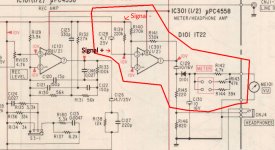

The opamp appears to be run off a single rail which I assume is 20 volts (we can't see that on the circuit you have attached).
The line you have marked as signal - looks like a virtual ground point and so should be at a reference value of 10 volts. Have you provided that?
The signal is applied to pin 3 via a cap.
How you connect the signal ground depends on the power supply you are using which is single rail as shown. That means you should be using 0 volts (pin 4 of the opamp).
The gain can be increased by lowering R140 but you must have all the other conditions satisfied first.
Hello,
Thank you for the reply Moole 🙂.
For now the opamp is powered by 12 volts DC on PIN8.
I need to change the power supply to 20V one.
I did not provided 10V to signal "-" mark because I was afraid that this will damage my amplifier and µPC4558 opamp. So can I simply apply 10V to the R139 resistor? This will not cause damage to other units connected? Where signal grounds should be connected then?
Signal grounds are connected to PIN 2 and 6. Should they be connected to the PIN 4 like power supply ground?
I don't know why but I was think that R141 is changing the gain, thanks for correction.
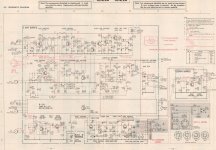
I've attached full schematic diagram, hope this will help a little.
Thank you for the reply Moole 🙂.
For now the opamp is powered by 12 volts DC on PIN8.
I need to change the power supply to 20V one.
I did not provided 10V to signal "-" mark because I was afraid that this will damage my amplifier and µPC4558 opamp. So can I simply apply 10V to the R139 resistor? This will not cause damage to other units connected? Where signal grounds should be connected then?
Signal grounds are connected to PIN 2 and 6. Should they be connected to the PIN 4 like power supply ground?
I don't know why but I was think that R141 is changing the gain, thanks for correction.
I've attached full schematic diagram, hope this will help a little.
Attachments
Last edited:
Did you connect pin 4 to ground?
Point that you marked as "signal minus" is +10V from power supply.
That is half of the 20V, so if you plan to use 12V than this must be 6V.
That voltage will not kill your amplifier, there is capacitor C128 that protect previous stage.
R141 is the for the gain of the meters amp, but usually is changing R140 for that.
PIN 4 is connected to the power supply minus.
So I need to connect 12V before the R139 resistor? Or better using voltage regulator like LM7806 to do that? Then connect LM7806 output to the R139?
And connect signal plus to the negative pin of C128?
Sorry for lame questions, I'm more mechanical person than electronical 🙂.
So I need to connect 12V before the R139 resistor? Or better using voltage regulator like LM7806 to do that? Then connect LM7806 output to the R139?
And connect signal plus to the negative pin of C128?
Sorry for lame questions, I'm more mechanical person than electronical 🙂.
The opamp is just to add gain and a low output impedance to drive the meter circuit.
Forget the circuit that was in their and just configure the opamp to suit what you are working with.
The most important question is what power supply voltage do you have to work with. Is it a single voltage rail like +12 volts or +30 volts or is it a split rail supply such as -12/+12 volts.
Forget the circuit that was in their and just configure the opamp to suit what you are working with.
The most important question is what power supply voltage do you have to work with. Is it a single voltage rail like +12 volts or +30 volts or is it a split rail supply such as -12/+12 volts.
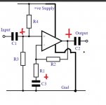
It needs to look like this.
Make R2, R3 and R4 = 100k
Make R1 variable. This sets the gain. Try a 47k preset and set it midway.
Make C1, C2 and C3 = 10uF.
Supply voltage can be anywhere from 9 volts to 36 volts. Make sure the caps are rated to suit the supply.
If it is working properly you should measure approx. half the supply voltage at all pins.
Attachments
Power supply is just single rail +12V.
So build it like I show above and use 16 volt caps. The resistors are not critical but R3 and R4 must be equal in value.
Thank you Molly for the detailed alternative schematics! I will use it if i will fail with original circuit 🙂.
For now I've recreated connections like it was in the deck.
So, to the PIN 8 I have +16V connected from single rail power supply.
Resistors R139 and R140 are connected to power supply by a simple voltage divider to achieve 8V on PINs 1,2 and 3.
I've measured voltages on the places like it is on the schematics and they are correct.
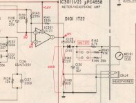
Resistors R145 and R146 are not present so I shorted them by adding 100K resistor to cathode of D101 to be connected to the ground. Everything is showed on the image.
Signal and power supply grounds are connected to PIN4 of the opamp.
The problem is that the meter is moving in wrong way, despite the correct connections of meter to the output of the opamp. I have no idea why it behaves like that. Is this possible that the rectifier is giving only negative output to the meters? I didn't change solder direction of D101.
Regards
For now I've recreated connections like it was in the deck.
So, to the PIN 8 I have +16V connected from single rail power supply.
Resistors R139 and R140 are connected to power supply by a simple voltage divider to achieve 8V on PINs 1,2 and 3.
I've measured voltages on the places like it is on the schematics and they are correct.
Resistors R145 and R146 are not present so I shorted them by adding 100K resistor to cathode of D101 to be connected to the ground. Everything is showed on the image.
Signal and power supply grounds are connected to PIN4 of the opamp.
The problem is that the meter is moving in wrong way, despite the correct connections of meter to the output of the opamp. I have no idea why it behaves like that. Is this possible that the rectifier is giving only negative output to the meters? I didn't change solder direction of D101.
Regards
Attachments
Yes, the final output of the circuit is a negative voltage so the meter will have to be wired the wrong way around. The diode charges the cap C130 to the peak of the AC signal voltage but the polarity of the diode gives a negative voltage.
So make sure you have the cap fitted correctly, plus end to ground.
(It might be worth you adding a small cap (say 22uF) to decouple your new divider to ground as you are sharing it with both opamp inputs)
So make sure you have the cap fitted correctly, plus end to ground.
(It might be worth you adding a small cap (say 22uF) to decouple your new divider to ground as you are sharing it with both opamp inputs)
Hello,
Well the divider is separated to the PIN4 of the opamp by 100uF 25V cap.
It seems that the opamp reacts incorrectly to the signal.
When I provide 1kHz 0,775V signal, the meter jumps and then slowly falls to almost -20.
I've attached a video to better present the problem.
Does this mean that the opamp is overloaded?
Another thing is when I disconnected the power supply the meters are jumping to maximum for a milisecond and falls to -20 VU.
Attachments
I don't think it will be overloading, there isn't enough gain for that.
All the opamp does is amplify the audio signal a little and also provide a low impedance drive.
Why not try just your meter circuit without the opamp and drive it from a power amp (connect it across the speaker) and see what happens. Just feed the audio into C129.
All the opamp does is amplify the audio signal a little and also provide a low impedance drive.
Why not try just your meter circuit without the opamp and drive it from a power amp (connect it across the speaker) and see what happens. Just feed the audio into C129.
The diode/s rectifiers inherently do that but as always, a simple passive circuit isn't all that great.
A simple passive logarithmic VU-meter
A simple passive logarithmic VU-meter
Thanks for the link Mooly. So, it’s more eye candy than an exact meter. Did a quick Google, it seems there are log opamp chips available. Have to check if they do lin -> log, or log -> lin.
Yes, most meters are just eye candy. If you do a search for 'opamp log convertor' you will turn up a lot of info... which you may already have done by the sound of it.
VU has a logarithmic scale. How do you convert the linear input signal to a logaritmic one?
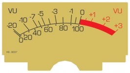
VU scale is Linear. Note that 10%-100% is dead linear, -20VU and -10VU are very close together, closer than +2VU and +3VU.

The diodes don't work to log the reading. They weaken the bottom 10% making -20VU even closer to -10VU.
BBC PPM and similar from other lands do have semi-log conversion. This costs more, and was not common on older tape recorders.
Attachments
Last edited:
- Home
- Source & Line
- Analog Line Level
- Reusing VU meter drive circuit from tape deck